1. Introduction
This article introduces the COP Watchdog module of the NXP KW38 chip. The KW38 wireless MCU not only integrates Bluetooth Low Energy 5.0 but also features a FlexCAN module. This design enables the KW38 MCU to be easily integrated into automotive or industrial CAN communication networks. The FlexCAN module supports CAN FD, enhancing bandwidth and reducing latency. The examples in this article use MCUXpresso IDE as the development environment. MCUXpresso IDE provides developers of NXP MCUs based on the Arm Cortex-M core with an easy-to-use Eclipse-based development environment, including support for general-purpose, crossover, and wireless MCUs. MCUXpresso IDE offers advanced editing, compiling, and debugging features, along with MCU-specific debug views, code tracing and analysis, multi-core debugging, and integrated configuration tools.
The watchdog is a critical hardware feature used to monitor the operational status of embedded systems. It ensures system stability and reliability by periodically checking system activity, such as whether the program is running correctly or if any faults have occurred. If the system fails to "feed the watchdog" within the specified time, the watchdog will trigger a reset signal, forcing the system to restart and avoiding prolonged crashes or unresponsive states. The KW38 includes a COP Watchdog module, where COP stands for "Computer Operating Properly." Next, we will introduce the COP Watchdog module in detail.
2. Overview of the COP Watchdog
The purpose of the COP Watchdog is to force a system reset when the application software does not execute as expected. To prevent the COP timer from triggering a system reset (when enabled), the application software must periodically reset the COP counter ("feed the watchdog"). If the application fails to reset the counter before the COP timer times out, a system reset will be generated, forcing the system to restart.
3. COP Watchdog Registers
SIM_COPC Register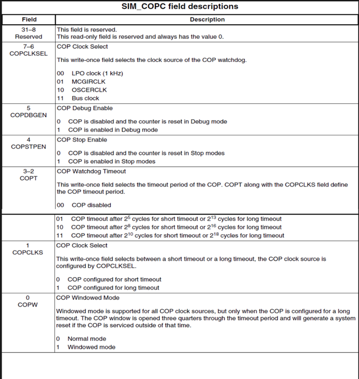
BIT0 (COPW): COPW=0 indicates standard mode, while COPW=1 indicates window mode. In window mode, the window opens at three-quarters of the timeout period, and the COP can only be refreshed during this time. Refreshing the COP at any other time will cause a system reset.
BIT1 (COPCLKS): COPCLKS=0 configures the COP for short timeout mode, while COPCLKS=1 configures it for long timeout mode.
BIT2-3 (COPT): The COPT and COPCLKS fields together define the COP timeout period. BIT2-3=00 disables the COP. BIT2-3=01 triggers a short timeout after 2^5 cycles or a long timeout after 2^13 cycles. BIT2-3=10 triggers a short timeout after 2^8 cycles or a long timeout after 2^16 cycles. BIT2-3=11 triggers a short timeout after 2^10 cycles or a long timeout after 2^18 cycles.
After any reset, the COP Watchdog is enabled. If the COP Watchdog is not needed in the application, it can be disabled by clearing the [COPT] bits in the SIM_COPC register.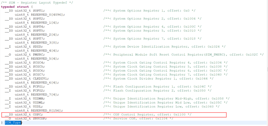
BIT4 (COPSTPEN): COPSTPEN=0 disables the COP in stop mode and resets the counter. COPSTPEN=1 enables the COP in stop mode.
BIT5 (COPDBGEN): COPDBGEN=0 disables the COP in debug mode and resets the counter. COPDBGEN=1 enables the COP in debug mode.
BIT6-7 (COPCLKSEL): These bits select the clock source for the COP. COPCLKSEL=00 configures the clock source as LPOclock (1Hz), which is the default configuration. COPCLKSEL=01 configures the clock source as MCGIRCLK. COPCLKSEL=10 configures the clock source as OSCERCLK. COPCLKSEL=11 configures the clock source as the Bus clock.
SIM_SRVCOP Register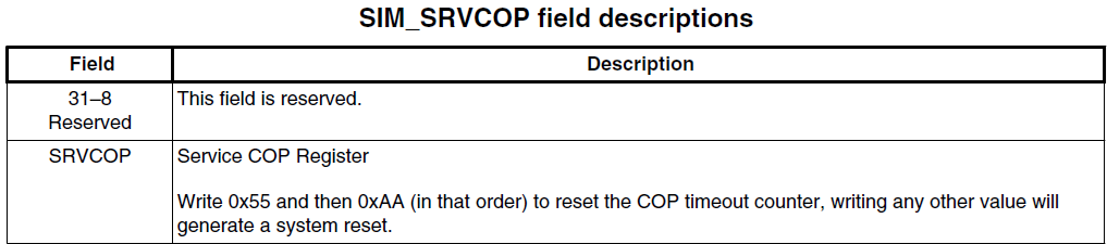
By writing 0x55 and 0xAA (in this order) to the COP (SIM_SRVCOP) register address within the selected timeout period, the COP counter can be reset. The write operation does not affect the data in the SRVCOP register. Once the write sequence is completed, the COP timeout period restarts. If the program fails to perform this reset within the timeout period, the microcontroller will reset. Additionally, if any value other than 0x55 or 0xAA is written to the SRVCOP register, the microcontroller will reset immediately.
4. COP Watchdog Example Demonstration
Preparation for the demonstration:
- MCUXpresso IDE with the FRDM-KW38 SDK installed. For downloading and installing MCUXpresso IDE and SDK, please refer to the "MCUXpresso_IDE_Installation_Guide," which will not be elaborated on here.
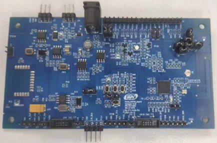
- WPI Foxe_KW38_Board.
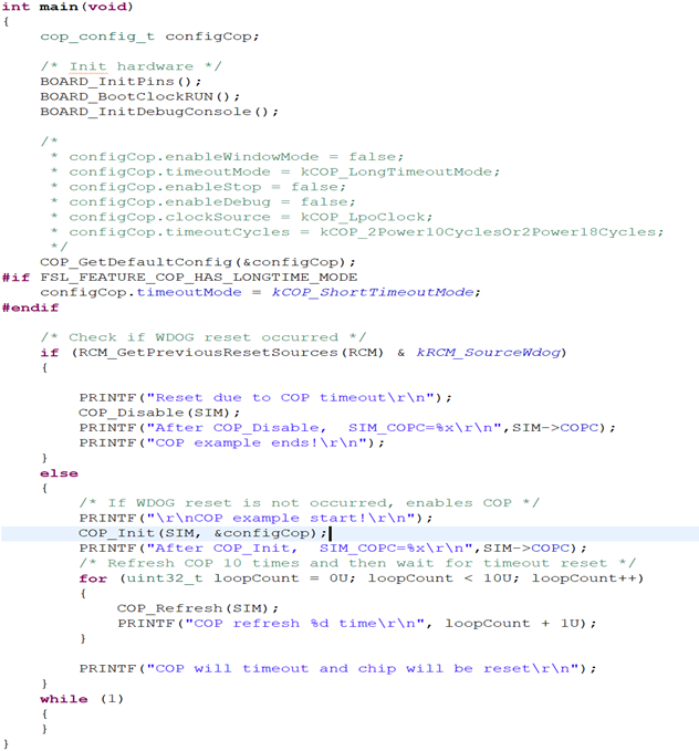
Below is the main function of the COP example:
The results after flashing and printing are as follows: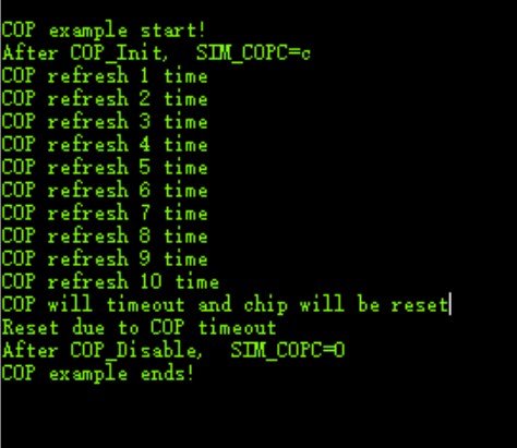
After powering on the chip, the watchdog reset is detected. If no watchdog reset is detected, the COP is enabled. After executing COP_Init, the default value of the SIM_COPC register is 0xC, consistent with the description above. After feeding the watchdog ten times, the system waits for the watchdog reset. Once the watchdog reset occurs, the main function is re-executed. Upon detecting the watchdog reset, COP_Disable is executed, and the SIM_COPC register is set to 0x00, disabling the COP as expected.
5. Summary
In this article, we introduced the important registers of the COP Watchdog and demonstrated its application through an example. The COP (Computer Operating Properly) Watchdog is a critical feature for monitoring system operation to ensure stability and reliability. By periodically checking system activity, it prevents issues such as program crashes or infinite loops. Most of the content in this article is based on official NXP documentation, and we hope it provides some insights for your learning and practice.
6. Reference Documents
[1] MKW38A512RM.PDF
Feel free to leave comments below the blog, and we will respond to your questions promptly.
For further inquiries, please contact the ATU department of WPI Group: atu.sh@wpi-group.com Author: mose
For more information, scan the QR code to follow us!