
i.MX RT1170The series of microcontrollers introducedXRDC2(Extended Resource Domain Controller 2It provides an integrated and scalable architectural framework for access control, system memory protection, and peripheral device isolation.XRDC2Allow the software toMCUResource allocation for processingdomainthereby supporting a secure operating environment. This article will provide a detailed introduction.XRDC2Its functions, operating principles, and example applications help readers better understand and use it.

Two.Main Function
XRDC2Key featuresIncluding:
- Resource Allocation: Allocating processor resources to processing.domain, each processdomainAssign a uniquedomainLabelDID)。
- DIDUsage:DIDIt is a new attribute related to data transmission across various systems, and is associated withuser/privileged、secure/nonsecureAttribute combination is used for access control.
- Access permissions: Access permissions to subordinate memory and peripheral targets are determined by the access-configured regions or memory blocks.(memory slot)Descriptor determines.
- Shared Support: Dynamically determine access permissions to enable the use of exclusive access locks for shared memory regions and peripherals.
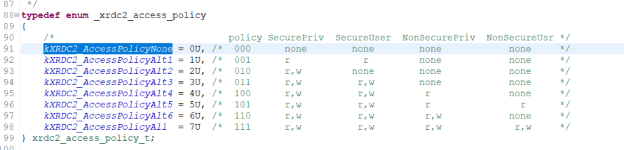
- Layered Access Model: Based on 4 Hierarchical Access ModelSecurePrivileged > SecureUser > NonsecurePrivileged > NonsecureUser) Construct, and inXRDC2In terms of eachdomainof3 bitAccess ControlPolicy(DxACP)。
- Global and individual description of locks: AlldomainLock the configuration register with individual descriptors.
- Distributed Programming Model: A software model and hardware implementation distributed across multiple submodules, supporting a wide range of highly configurable architectures, scalable hardware design and implementation, and extensibility to various applications.SoCEquipment.
Three.Operation Module Description
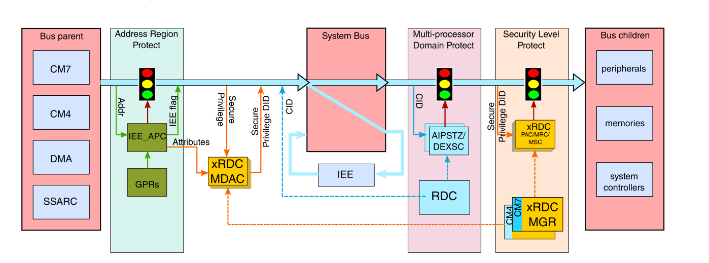
3.1 Memory protection mechanism
XRDC2The memory protection mechanism consists of two parts:
· MDACAssign for each bus eventDID(domain identifier) and access properties.
· Access Control Module: IncludesMemory Region Controller(MRC)、Peripheral Access Controller(PAC) andMemory Slot Controller(MSC), according toDIDEnforce access control policies with event attributes.

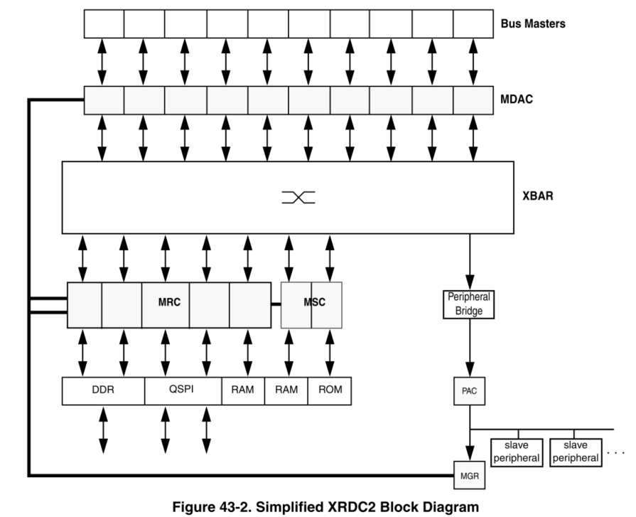
3.2 Master Domain Assignment Controller(MDAC)
MDACResponsible for generating each system bus eventDIDNon-secure and privileged attributes. The main behaviors are as follows:
1. Match input:MDACAccording to each enabledMDADescriptor Matching Field (MATCH field) and mask field (MASK field) For eachBusThe events are being matched and compared.
2. GenerateDIDWhenMDACMatching input with all bit positions.MATCHWhen the fields match,MDAGenerate a hit. Highest priority.MDAEffective upon activation, itsDID、PA(Privilege attribute)SA(Safety attribute) The field value determines the bus event.DID, non-secure and privileged attributes.
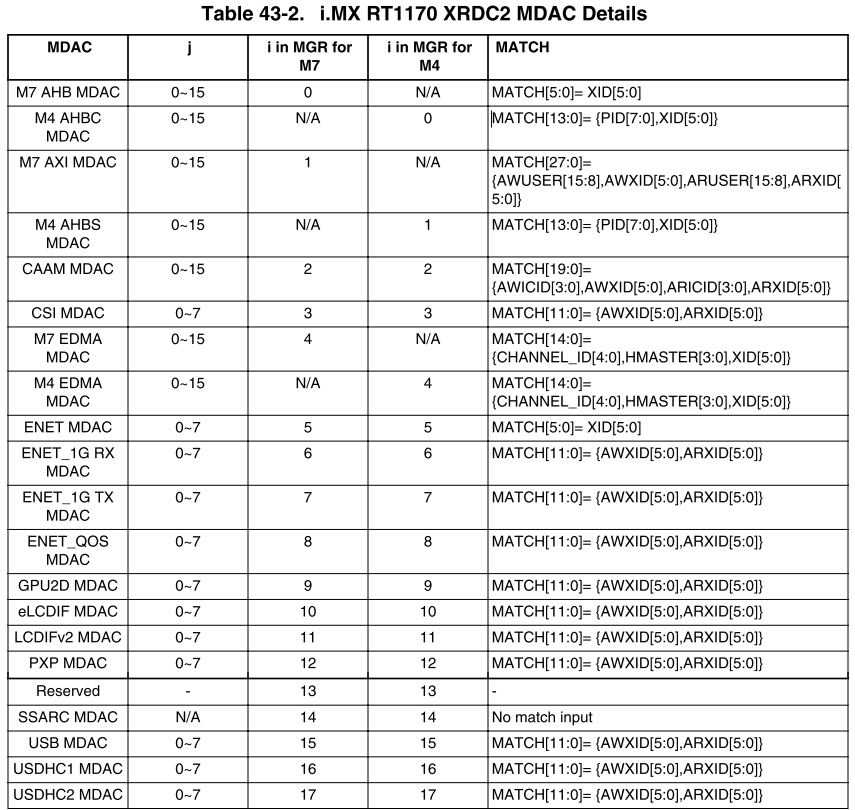
The table below showsRT1170ofMDACMatch, depending on the hardware, it can be compatible.(MATCH)The quantity is different.

3.3 Memory Region Controller(MRC)
MRCProvide a basis for all bus references targeting non-peripheral device memory space.domainHardware access control. Using pre-programmed memory region descriptors.MRGDDefine memory space and its associated access permissions. When the system accesses it,MRCThe specific actions are as follows:
1. Regional hit detection:MRCThe current system reference address is detected to see if it hits a specific memory region by comparing it with the start and end addresses defined in the descriptor.
2. Priority assessment: If multiple areas are hit,MRCSelect the highest-priority descriptor for evaluation.
3. Permission check: Based onDxACPFields and access attributes (read/Write, safety/Unsafe, user/Privileges), evaluate access permissions. If the permissions are sufficient, allow access; otherwise, generateBus Fault。
3.4 Memory Slot Controller(MSC)
MSCPerform access control for memory spaces or peripheral devices with a fixed address range. For access within that address range,MSCUse and access relatedDIDChoose the appropriate one.DxACPField, and evaluate the validity of the access. If the access permissions are sufficient, allow access; otherwise, generateBus Fault。
3.5 Peripheral Access Controller(PAC)
PACPerform access control for a set of peripheral devices connected to the peripheral bus bridge or integrated into the peripheral subsystem.PACChoosePDACDescriptor, and use it in relation to access.DIDChoose the appropriate one.DxACPField, then evaluate the validity of the access. If the access permissions are sufficient, allow access; otherwise, generate.Bus Fault。
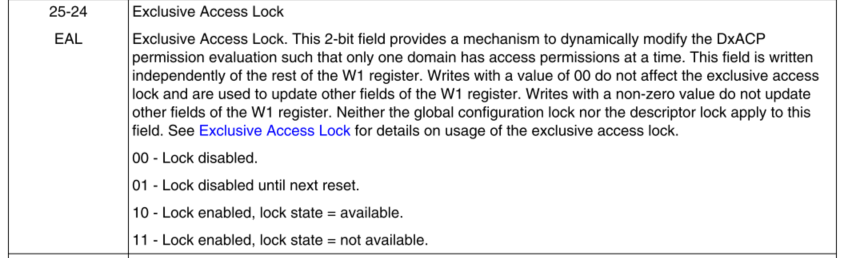
3.6 Exclusive Access Lock(EAL)
An exclusive access lock is used for dynamic modification.DxACPEvaluate to ensure there is only one at any given time.domainAccessible hardware mechanisms.

3.7 DxACPEvaluation
XRDC2The access control mechanism is based on4Level permissionsSecurePrivilegedSecurity Privileges)/SecureUser(Safe Use) /NonsecurePrivileged(Non-secure privilege)/NonsecureUser(Unsafe use)), permissions are based ondomainSettingsPolicyDecide whether you have the right to execute; the differences in permissions are shown in the table below.
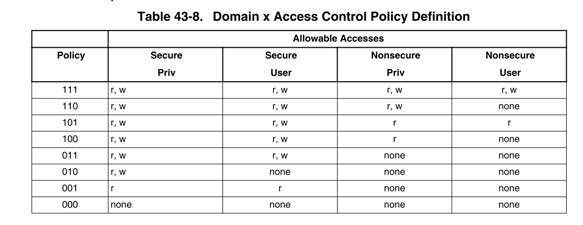

The user configures each component based on the requirements of the system architecture.domainofPolicy

In the systemAccess permission check willDxACPField values and event access attributes (read/Write, safety/Unsafe, user/Privileges) are compared. If the permissions are sufficient, access is granted; otherwise, an error is generated.Bus Fault。
3.8 Manager(MGR)
The complete programming model is very extensive and requires a64 KbyteThe subordinate peripheral register address space slot, although most devices define a sparsely distributed subset.
MGRThe submodule implements global registers. Other registers are distributed across various submodule instances.MSC、PAC、MDAC、MRC).MGRThe submodule provides the necessary hardware management for access to all programming models, generating and allocating appropriate address decoding and writing data to them.MSC、PAC、MDACandMRCInstantiate submodules, and collect and merge all register read data buses and responses.
3.9
Initialization and ConfigurationXRDC2The initialization process usually includes the following steps:
1. Allocate everything through descriptor configuration.domain(MDACi_MDAj_Wk), memory region (MRCi_MRGDj_Wk), surroundingsdomainAccess ControlPACi_PDACj_Wk) andMemory SlotAccess ControlMSCi_Wk)。

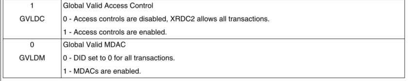
2. EnableXRDC2Will be set laterMCR [GVLDM] bit。
3. Set up according to the delay of the system data bus.MCR[GVLDC] bit, and makeXRDC2Fully operational.
Four.Example test
This implementation aims to achieve throughXRDC2Example explanation through configuration modificationBUSMethods of access control
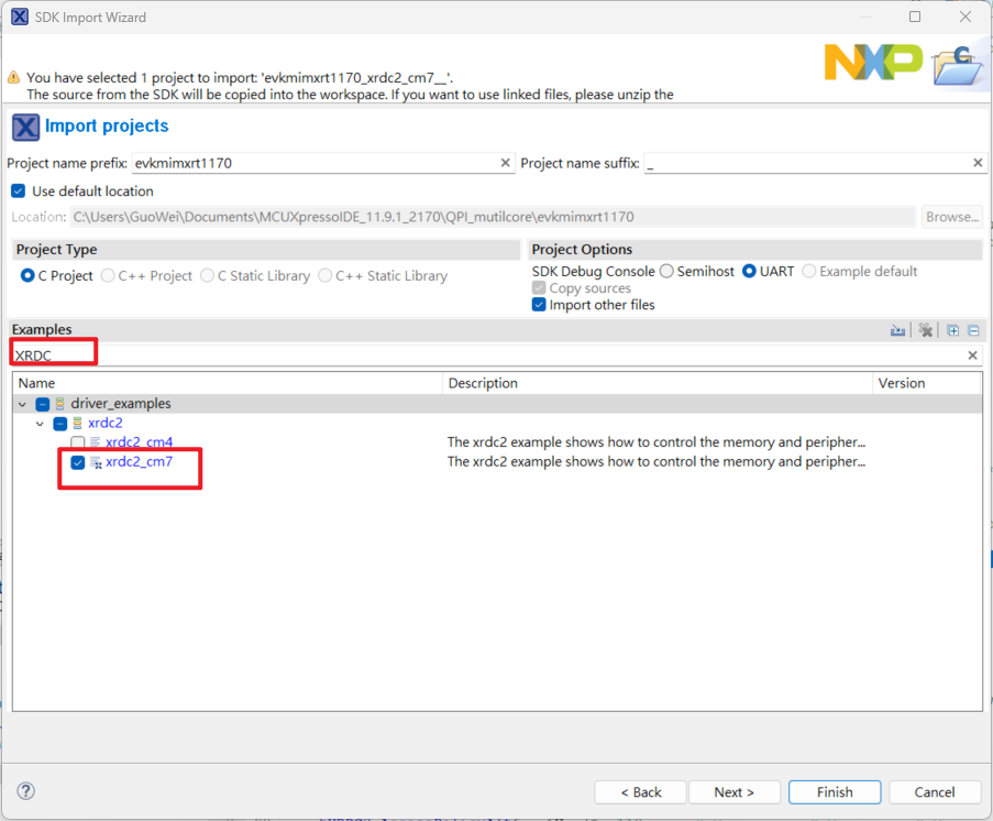
1. ImportXRDC2Example, clickImport SDK example, atSDK Import WizardChoose inRT1170Development board

2. InputXRDCChooseCM7Example
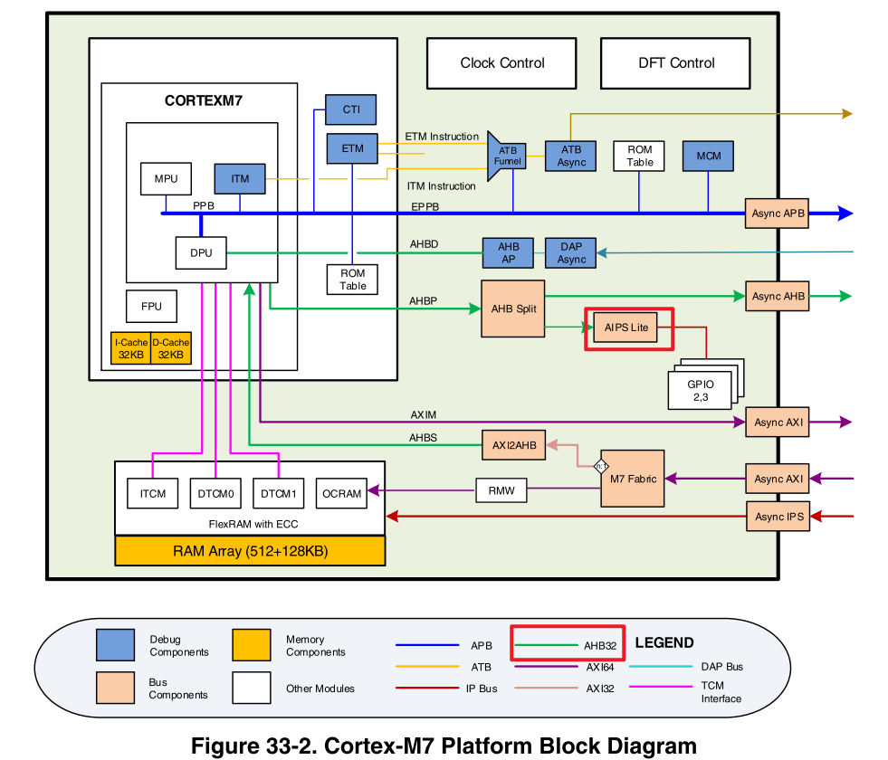
3. After loading the example, you can see the focus onM7 AXIAndM7 AHBPerform permission configuration, and proceed with subsequent configurations.memoryAndperipheralofPolicyIt will determine whether access is granted based on this permission.
Among themAXI BusResponsibleSDRAM / NAND/NOR/SRAM/SRAMWaiting for data transfer
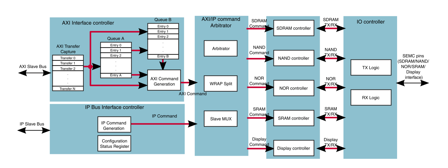
AHBThroughAIPS LiteConnect toperipheral, and then allocatePeripheralPermission
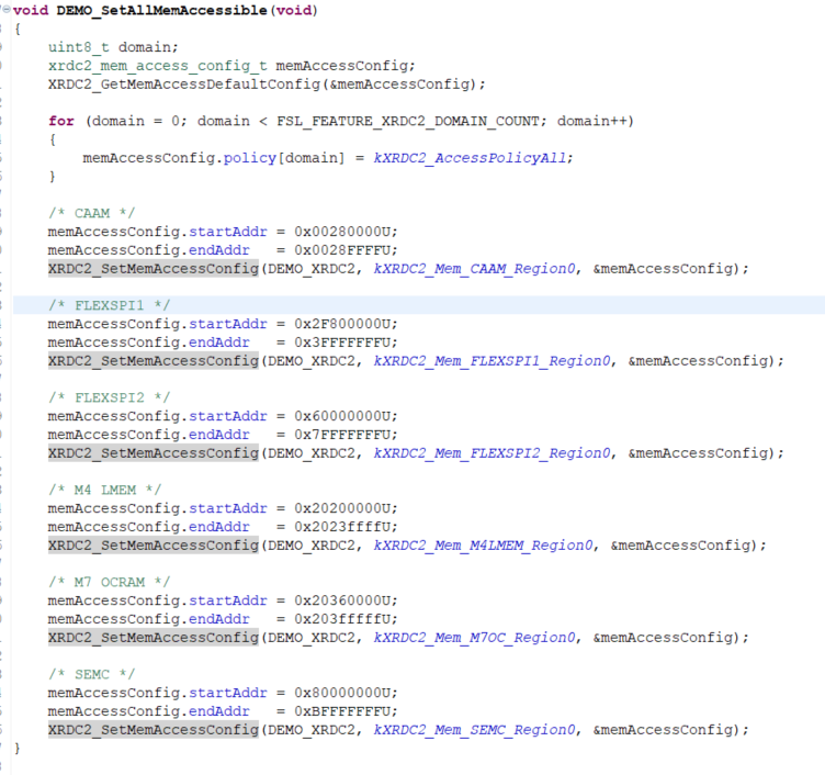
4. ModifymemoryAccess permissions, configured as all.policyAll are accessible, and multiple configurations can be displayed here.policy, according todomainDifferent permissions for different purposes, for convenience, all are grouped together.domain policyConfigured for full read and write.
5. ThroughXRDC2_SetGlobalValidFully initiate and confirm the current status.XRDC2ConfiguredDomain IDFor configurationID 2

The configuration part has been completed at this point.
6. Test memorymemoryPartially, first0x20200000 - 0x2023ffffConfigured to be completely inaccessible
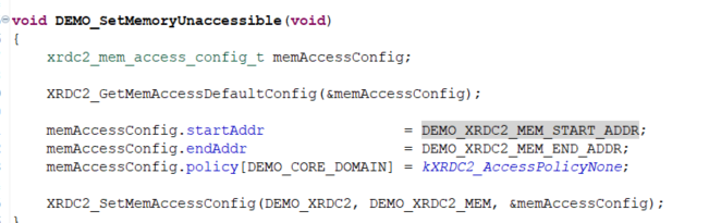
ClosecacheAvoid accessingcacheThe value, so it can be accessed directly.memoryLocation, direct readingmemoryLocation
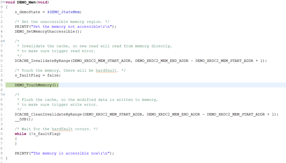
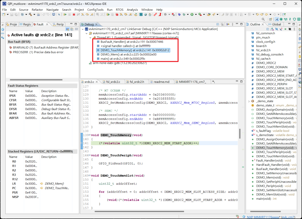
7. From the execution results, it can be seen that when executing toTouchMemoryTime to enterBusFaultIn this exampleoverride BusFault_HandlerLet it execute.Fault_Handler, here isdemoThroughflagDetermine the current generationerrorProcess the source further.
8. Follow-upDEMO_Periph,DEMO_MemSlotAll are the same mode of testing methods.
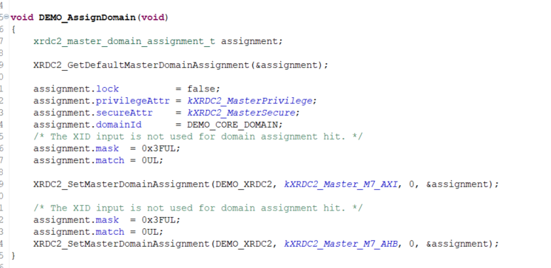
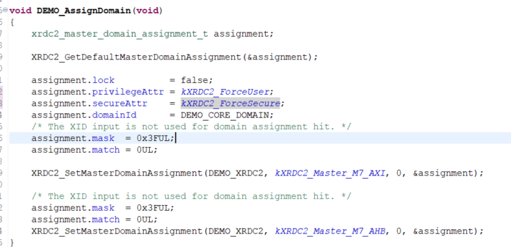
9. ModifyDEMO_AssignDomainWillprivilegeAttrModify as follows
assignment.privilegeAttr=kXRDC2_ForceUser; assignment.secureAttr =kXRDC2_ForceSecure; |
10. Willmemory policyModify tokXRDC2_AccessPolicyAlt3,DEMO_SetMemoryUnaccessibleModify it as shown in the image below.
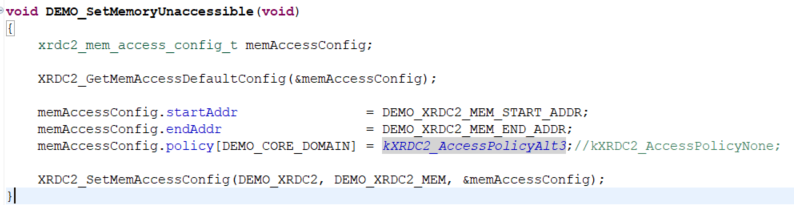
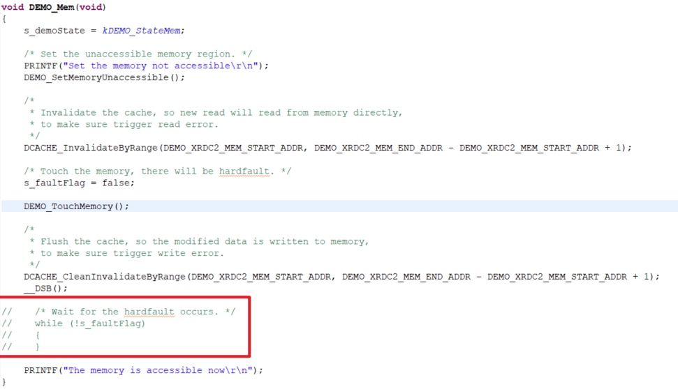
WillDEMO_MemUsed for waiting in the middle.whileRemove, thiswhileThe circle is just waiting.BusFault_HandlerGenerate, removing it does not affect the whole.demo
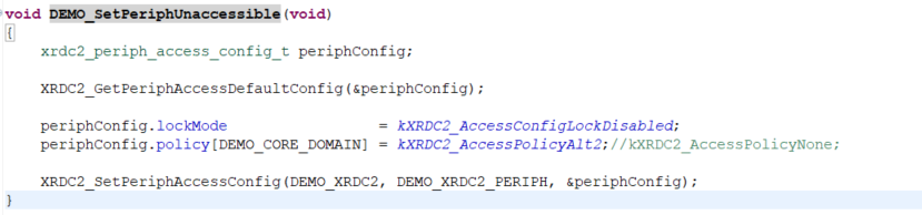
11. WillperipheralModify tokXRDC2_AccessPolicyAlt2,DEMO_SetPeriphUnaccessibleModify as shown in the image below.
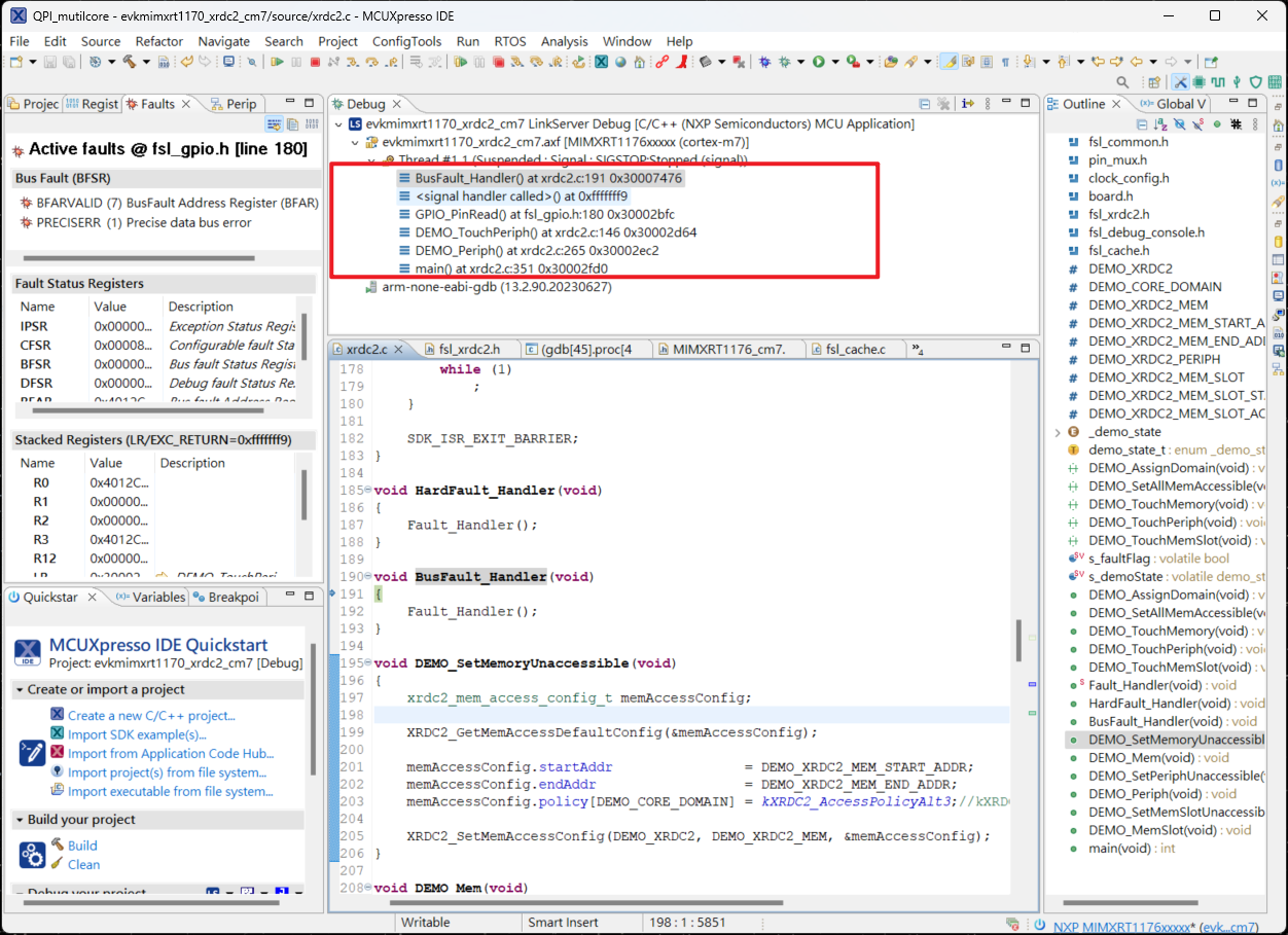
12. These two settings perfectly reflect it.PolicyThe impact of configuration on access control can be observed after execution.memoryDue to configurationkXRDC2_AccessPolicyAlt3Visiting at this time will not trigger.BusFault_HandlerandperipheralBecausepoliceConfiguration, the current access permissions do not allow and triggered.BusFault_Handler
Readers can modify the pairing themselves to gain a better understanding.XRDC2On the functionality of resource management.