1. Tools Section
This chapter determines whether the I-jet and adapter are compatible with the J-LINK socket on the E3640 development board.
1. I-jet Adapter
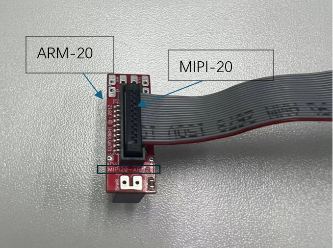
Figure (1)
The front panel of the I-jet is equipped with a MIPI-20 connector, along with MIPI-20 and MIPI-10 cables, as well as a traditional Arm-20 adapter. All other available I-jet adapters are also compatible with the I-jet Trace. Here, we are using the Arm-20 adapter.
2. MIPI-20 to ARM-20 Adapter
The I-jet comes with a MIPI-20 to ARM-20 adapter. It converts the MIPI-20 I-jet cable to a traditional ARM-20 (2.54mm × 2.54mm pitch) JTAG header. The part number is HTST-110-01-L-DV, and the connection diagram of the adapter is shown below.
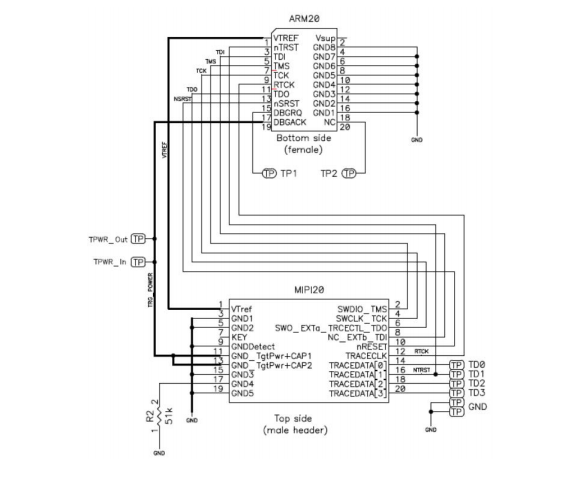
Figure (2)
3. E3640 Development Board J-LINK J402 Partial Schematic:
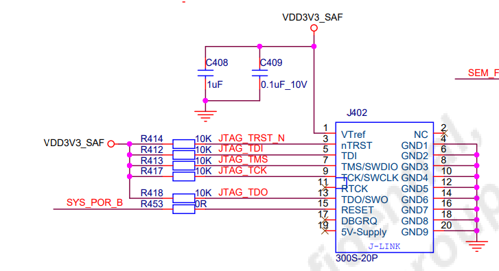
Figure (3)
ARM-20 is compatible with JLINK pins.
2. Code Section
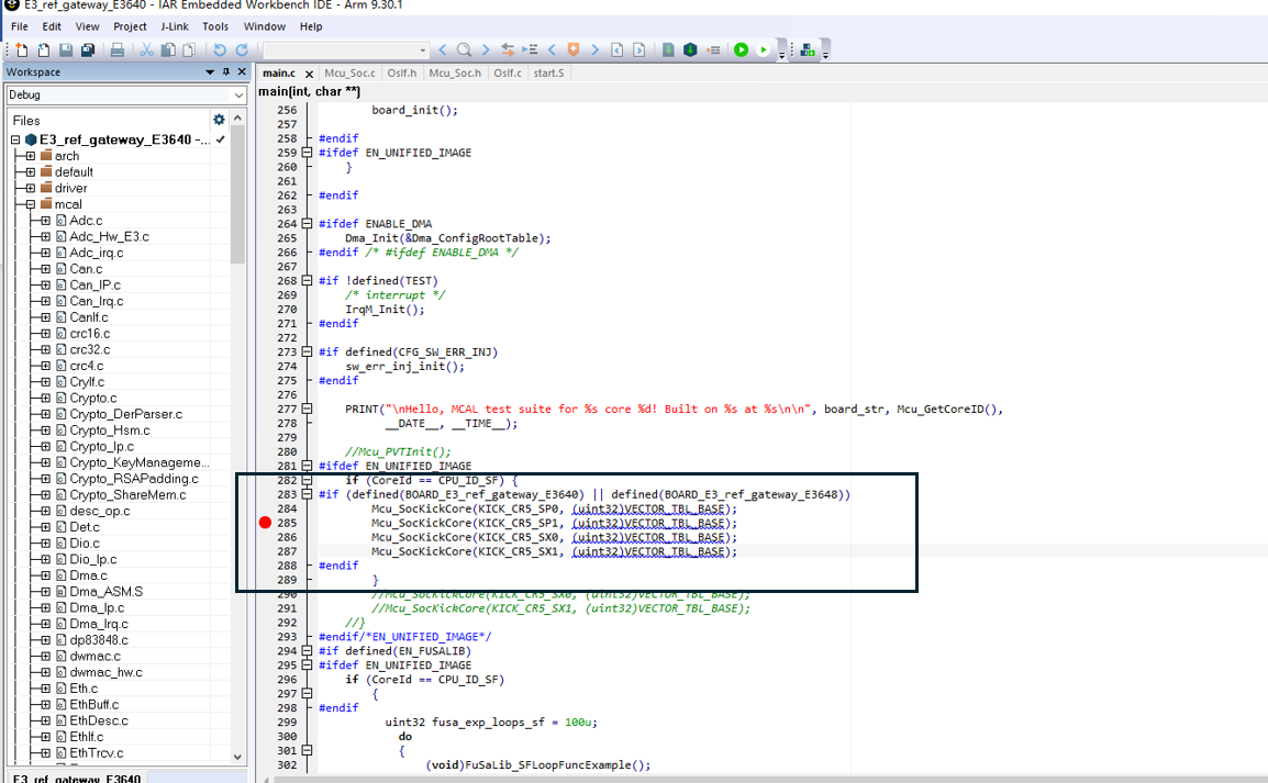
Figure (4)
Kick multi-core.
3. Configuration Section
It is necessary to download to flash and then attach to start.
Use mode 0000 for programming, select the SWD mode for the interface. JTAG mode may fail due to pin occupation, or it is recommended to use the SDTOOL tool for programming. When programming, select 1 core.
After starting 1 core, attach and bring up other cores.
Download:
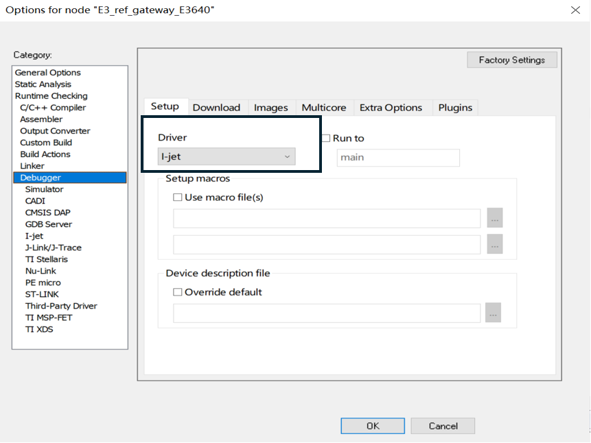
Figure (5)
Figure (6)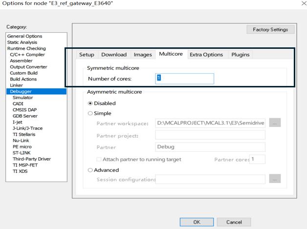
Figure (7)
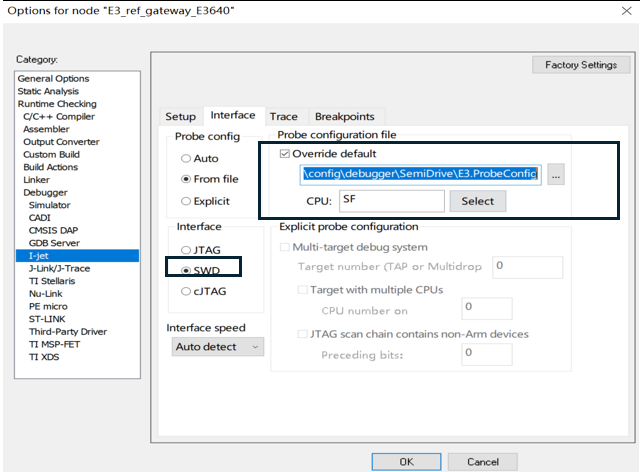
Figure (8)
Attach:
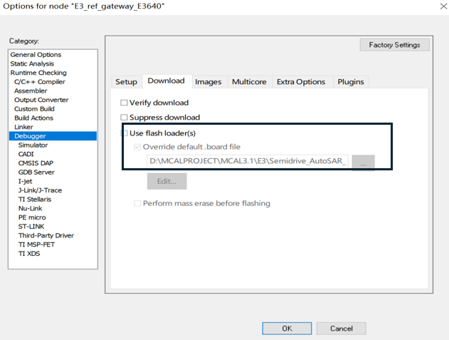
Figure (9)
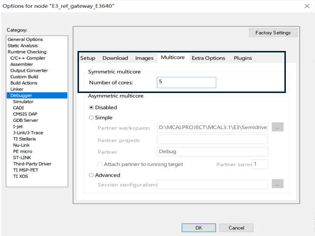
Figure (10)
4. Single-Core or Multi-Core Operations
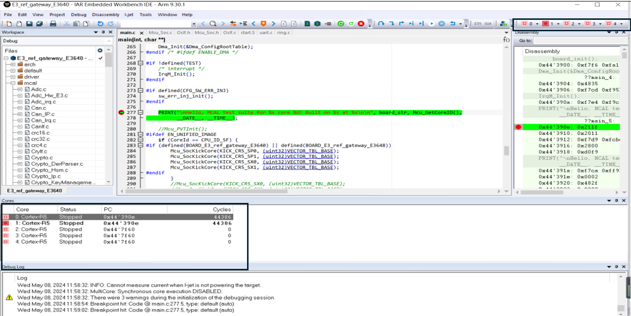
Figure (11)
5. References:
http://www.bmrtech.com/upload/tech_pdf/000/000/001/601282fd0cdfe.pdf
"E3 Mcal IAR + I-jet Multi-Core Debugging"
"Multi-Core Debugging in IAR Embedded Workbench for Arm"
Feel free to leave a comment below the blog, and we will respond to your questions promptly.
For further inquiries, please contact the ATU department of WPI Group: atu.sh@wpi-group.com Author: Purple
For more information, scan the QR code to follow us!