

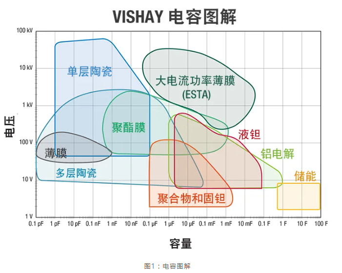
Figure 1 shows the typical capacitance and voltage ranges of commonly used capacitor dielectrics, often with several overlapping options.
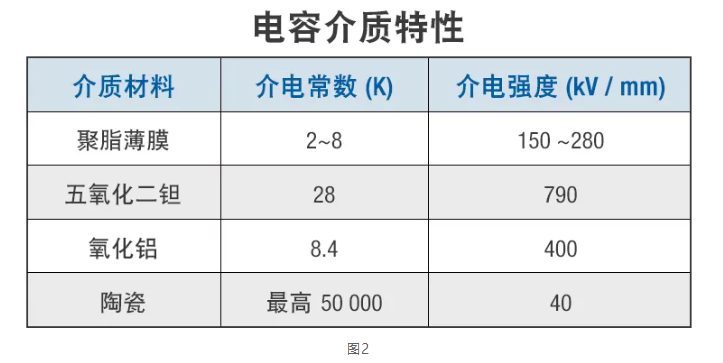
While capacitance and voltage are usually the primary parameters for device selection, many other parameters contribute to making the best choice. As shown in Figure 2, the typical dielectric constant (K) and dielectric strength values of four basic types of capacitors can be observed. A combination of low K value and low dielectric strength (e.g., polyester film capacitors) results in low volumetric efficiency. However, due to their very low losses, highly stable electrical characteristics, and low cost, these larger devices are still widely recognized.
In operation, the equivalent series resistance (ESR) of a capacitor is the real part of the impedance, representing the losses in the capacitor's equivalent circuit. These parameter values vary with temperature, frequency, and dielectric type. Insulation resistance (IR) determines the DC leakage current through the capacitor under the applied voltage, and the leakage current of electrostatic (film and ceramic) capacitors is typically much lower. DC leakage current varies with temperature and the magnitude of the applied voltage, while inductance is related to the type of electrodes used.
Figure 3 illustrates the important relationships between capacitive reactance, dissipation factor, inductive reactance, and impedance. A very high resistance value is used to model insulation resistance. For convenience, it can be ignored when deriving the total impedance (Z).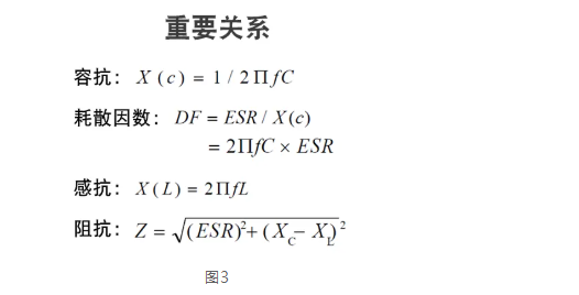
Impedance is a critical indicator for determining the impact of a capacitor on the input signal. In charge/discharge cycles, low ESR is essential for achieving high efficiency, low heat loss, and reliability. Capacitive reactance (XC) and inductive reactance (XL) represent the energy storage capacity and the induced magnetic field generated by the capacitor. Notably, when XC and XL are equal, the device reaches its resonant frequency. This is particularly important when selecting decoupling capacitors to eliminate AC noise components in DC signals.
To effectively eliminate AC signal components in DC links, capacitors with a resonant frequency close to the frequency of the AC noise to be removed should be selected to achieve low impedance and effective decoupling to ground.
Automotive application types are typically divided into powertrain control (ECU and transmission) and safety/comfort control (e.g., airbags and temperature control). Application type is important when considering critical performance, reliability, and accuracy. Another major distinction is the location within the vehicle and the resulting operating conditions. Engine bay applications may be exposed to or immersed in salt spray, water, fuel/oil, with operating temperatures reaching 125°C or higher, and vibration forces up to 15 g at frequencies as high as 200 Hz. These conditions differ significantly from those in the cabin.
In fact, another high-capacitance technology (double-layer capacitors, EDLC) is limited to cabin applications, such as electronic lock power backup, due to its operating temperature limit of 85°C.
In general, electrolytic capacitors (tantalum, aluminum, and EDLC) have high capacitance but are polarized, while electrostatic capacitors (polyester film and ceramic) are non-polarized and typically have very low ESR and impedance.
Electrolytic Capacitors
Tantalum devices are recommended to be used with voltage derating, with solid tantalum capacitors derated by 50% and polymer and liquid tantalum axial capacitors derated by 80% to ensure reliability. To achieve the extremely low ESR often required for high-capacitance devices, capacitors need to undergo surge testing/screening. Under voltage derating, the typical failure rate is 5 FIT (one failure per billion operating hours) to 15 FIT, and their electrical characteristics are very stable over time and temperature.
High capacitance is the main feature of aluminum electrolytic capacitors; however, temperature significantly affects device performance. Different product series have operating temperatures of 85°C, 105°C, 125°C, and 150°C. Within the entire rated temperature and ripple current range, the devices have a normal wear-out lifespan of up to 10,000 hours, eliminating the need for current screening. Lifespan can be extended by reducing any one parameter.
Electrostatic Capacitors
Ceramic capacitors do not require voltage derating to ensure reliability, but the voltage coefficient of capacitance must be considered, as capacitors may lose up to 40% of their capacitance when operating at or near their rated voltage. The typical failure rate is less than 1 FIT, and some ranges can easily operate at 150°C. Failure modes include short circuits or parameter drift.
Finally, polyester film capacitors typically have a rated temperature of 105°C, although PPS devices can operate at 125°C (PET) or even 150°C (PEN). Voltage derating is not required, and the typical failure rate is about 5 FIT, but surface-mount products are limited.
The importance of these characteristics depends on the application, required size, cost, and manufacturing process. However, when considering actual circuit functionality, these characteristics can indeed be used for general technical selection.
Power filtering requires high capacitance, low ESR, and high-temperature resistance, making tantalum, aluminum, and some ceramic capacitors suitable. High-capacity energy storage demands high capacitance and low ESR to meet the needs of rapid discharge and pulse applications, for which tantalum, aluminum, and some polyester film capacitors are widely used. Tuning and clock circuits require capacitance to be highly stable across temperature and frequency ranges and must be repeatable under thermal cycling.
In this regard, Class I (C0G/NP0 and high Q) ceramic and polyester film capacitors are usually the best solutions. Decoupling/bypass functions require very low ESR and good impedance (Z) performance. Ceramic, polyester film, and some specially designed tantalum polymer devices are ideal for this application. X/Y safety capacitors for EMI/RFI filtering require high voltage and pulse performance, for which only film and ceramic capacitors can be used.