1. Introduction
SENT stands for Single Edge Nibble Transmission, a point-to-point, unidirectional transmission protocol introduced by SAE. It is used for data transmission between in-vehicle sensors and electronic control units (ECUs). As a new automotive sensor interface standard (SAE J2716), SENT offers excellent EMC characteristics compared to AD and PWM outputs, reduces wiring harnesses and connector pins, and can transmit fault codes, providing strong diagnostic capabilities for sensor systems. Due to its simplicity and the aforementioned advantages, SENT can serve as a replacement for Analog Input and can partially replace CAN and LIN in localized systems. However, it cannot fully replace CAN or LIN because SENT is a continuous unidirectional transmission, whereas CAN and LIN are bidirectional.
E3 MCAL3.1 uses eTimer to capture SENT signals. On the falling edge of the SENT signal, an eTimer interrupt is triggered, and software decoding is performed in the interrupt handler.
2. Test Environment
Hardware: E3 Gateway A02 development board, as shown in Figure (1).
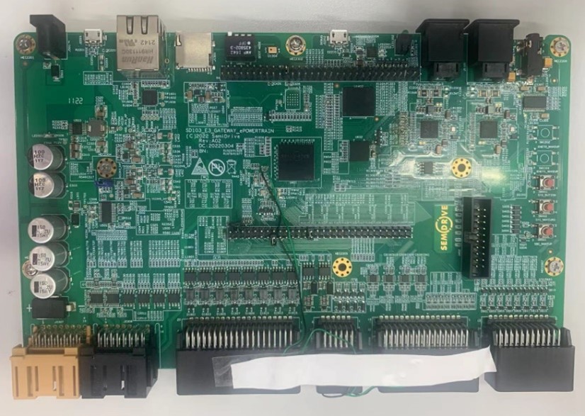
Figure (1)
Hella SENT sensor, as shown in Figure (2), outputs 1.65us tick 24-bit (6 nibbles) data.
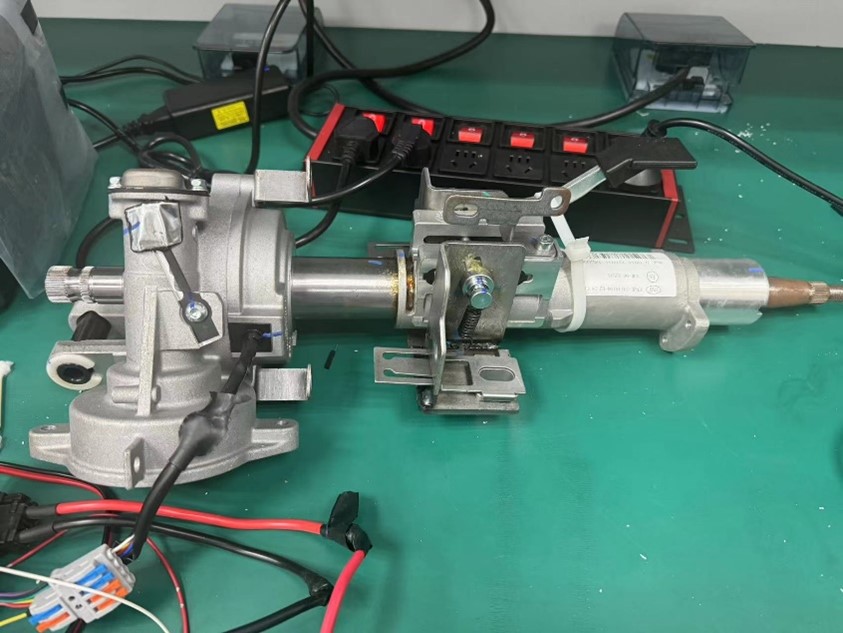
Figure (2)
Software: E3 MCAL3.1 e3_ref_gateway project.
3. EB Configuration
The configuration of the SENT function involves three modules: port, xTRG, and SENT. The configuration details are as follows:
- Port
GPIO-A11 is used as the input pin for the SENT signal. The relevant EB configuration is as follows, with the pin multiplexing set to xTRG_IO11.
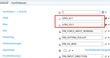
Figure (3)
- xTRG
After passing through GPIO_A11, the signal enters the A capture channel of eTimer1 via xTRG.
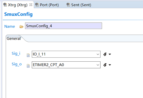
Figure (4)
3. SENT
SentTickFrequency represents the frequency of the SENT signal, which needs to match the sensor output. For a 1.65us tick, the reciprocal is 606060.
SentHardwareModule & SentHardwareChannel indicate the use of the A capture channel of eTimer2.
SentFastChannelFormat & SentDataBitNum specify the SENT data format.
SentSampleInterval & SentFilterBandwidth define the filter sampling interval and filter sampling bandwidth.
SentNotifyFrameOver is the interrupt callback function. After declaration, it needs to be implemented in the test program.
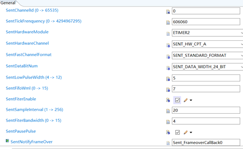
Figure (5)
4. Test Method
1. According to the schematic, connect the development board and the SENT sensor as shown in Figure (6).
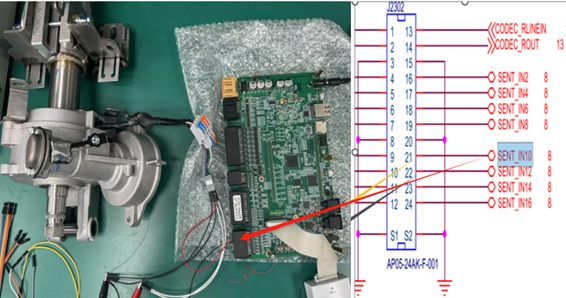
Figure (6)
- Test Code
The test code is located at ..\test_suite\example\sent_example\sent_example.c
The initialization process of the test code is shown in Figure (7).
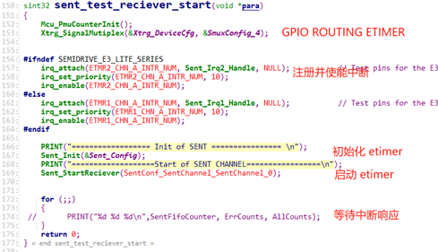
Figure (7)
The specific implementation of the callback function declared in the EB configuration is shown in Figure (8). The interrupt handler will call the corresponding callback function based on the channel (A, B, C, D) that generated the interrupt after parsing the data.
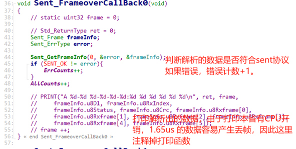
Figure (8)
3. Test Results
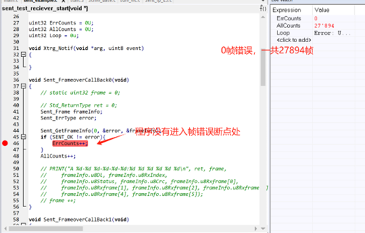
Figure (9)
5. References
- E3400_E3600_MCU_Technical_Reference_Manual_Rev00.12.pdf
- SemiDrive_E3_SSDK_User_Guide_Rev1.0.pdf
Feel free to leave a comment below the blog, and we will respond to your questions promptly.
For further inquiries, please contact the ATU department of WPI Group: atu.sh@wpi-group.com Author: Lao Ge San Wu Ping
For more information, scan the QR code to follow us!