
1. Overview
This article is a continuation of “MCX_A BLDC Motor Tuning Process - Part 1”, explaining the principles and content of PID control. Following the chapter flow, the motor FOC control algorithm will be tuned sequentially for the angle loop, current loop, and speed loop. The principles of field weakening control will also be introduced. Please follow the process outlined in this article to complete motor tuning.
2. Software and Hardware Requirements
For detailed hardware and software setup, please refer to WPG DadaTong’s “MCXA153 EVB Motor Development Guide”.
2.1 Software Requirements
Mcuxpresso SDK
Freemaster Version 3.2
SDK_2_16_000_FRDM-MCXA153
2.2 Hardware Requirements
FRDM-MCXA153
FRDM-MC-LVPMSM
24V adapter
3. PID Controller Parameter Tuning
There are many methods for tuning PID control algorithm parameters. Below are some quick tuning methods. PID consists of Kp, Ki, and Kd, where Kp is proportional control, Ki is integral control, and Kd is derivative control.
Adjusting Kp significantly increases or decreases the system's response speed and is closely related to maximum overshoot and oscillation.
Adjusting Ki controls the system by continuously integrating errors, which can increase or decrease response speed and eliminate steady-state errors.
Adjusting Kd reflects the derivative of the error, providing a rapid response to instantaneous errors. However, in noisy environments, it may destabilize the control system. Therefore, PI control is commonly used in motor control instead of full PID control.
3.1 Ziegler-Nichols Method
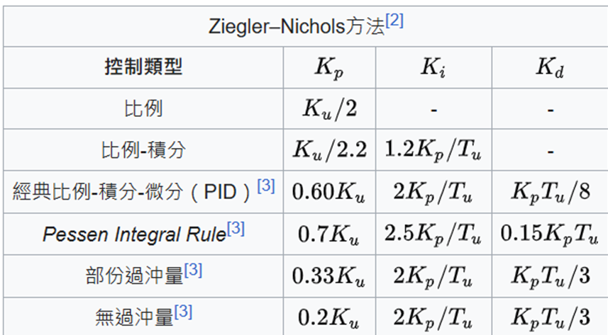
This tuning method involves first adjusting Kp while setting the other controller parameters to zero. Gradually increase Kp until the control output oscillates continuously without diverging. The oscillation period is defined as Tu, and the current Kp value is defined as Ku. The designed Kp controller is Ku / 2.
For motor control, a common PI controller is Kp = Ku / 2.2 and Ki = 1.2 Kp / Tu.
The table below is sourced from Wikipedia:
3.2 Lead/Lag Controller Design
3.3 Pole-Zero Controller Design
3.4 Root Locus Controller Design
The above controller designs require relevant algorithm tools for better computation. Since these tools need to be purchased, additional articles on control system and algorithm design will be added if needed in the future.
4. Angle Loop Tuning and Verification
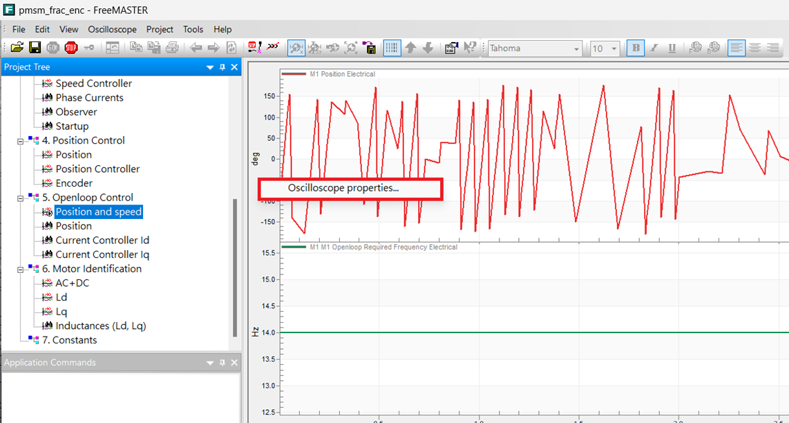
Angle loop tuning in open-loop Sensorless mode estimates the back electromotive force (EMF) by sampling three-phase currents. The back EMF is then used to calculate the current angle position, which is finally confirmed by the PLL (Phase-Locked Loop). Common methods for estimating back EMF include Observer and SMO (Sliding Mode Observer) algorithms. Following the process from the previous article, enter the open-loop operation mode. Use the MCX_A Freemaster motor tuning interface's oscilloscope function to verify whether the parameters operate normally or if the angle tracking speed is too slow, causing operation failure.
In the MCX_A Freemaster interface, right-click on the oscilloscope function graph to configure related content.
Under the Variables section, you can add parameters to observe in the Graph Block using the Add Variable option. You can also change the observed parameters in the Variable list.
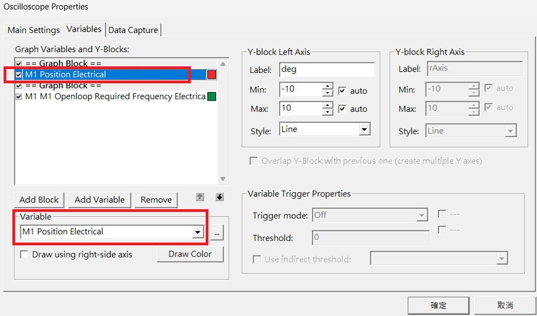
The parameter configuration for this article is shown below:
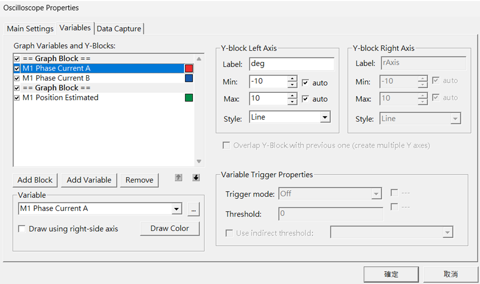
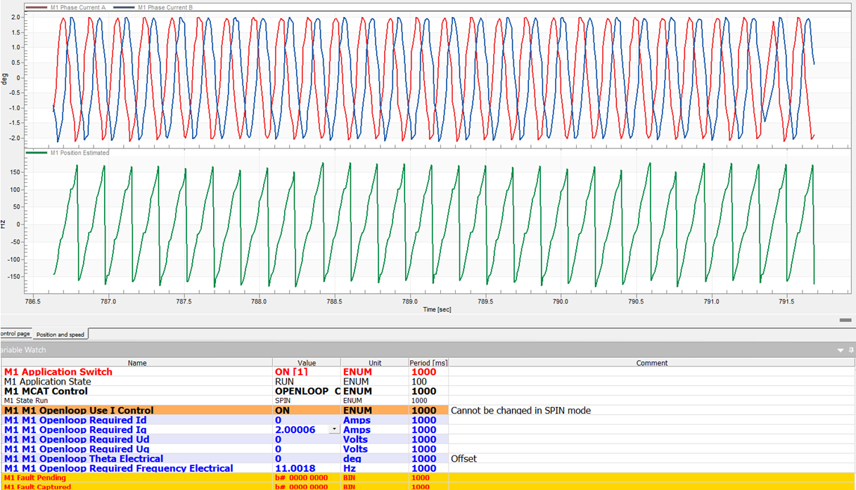
It is recommended to use open-loop current control to start the motor and obtain clean three-phase currents. Use these currents to estimate accurate angle information and verify whether the corresponding frequency matches, as shown below:
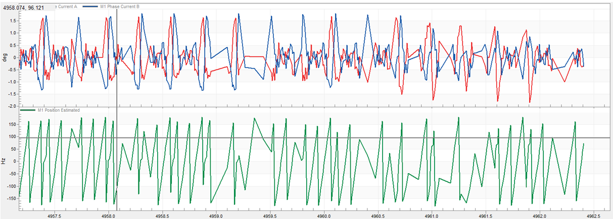
If the current signal feedback is abnormal, the angle information will also be incorrect. Using open-loop current control, if the current signal is normal but fails to generate correct angle information, Sensorless parameters need to be adjusted.
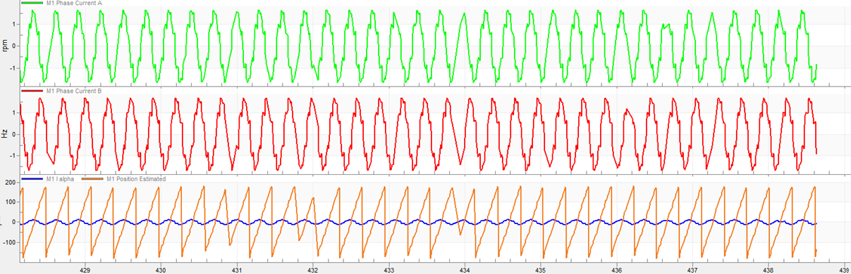
The adjusted graph for normal operation is shown below:
5. Current Loop Tuning and Verification
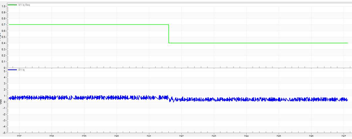
For current loop tuning, we mainly need to tune the Iq current PID controller parameters. By observing the Iq command and feedback values using PWM on an oscilloscope or Freemaster, we can verify the tuning. On the NXP MCX_A motor platform, use current control mode to check whether the Iq feedback follows the command, whether there is a steady-state error or oscillation, and ensure the controller does not diverge. Use PID tuning techniques to complete the current loop tuning.
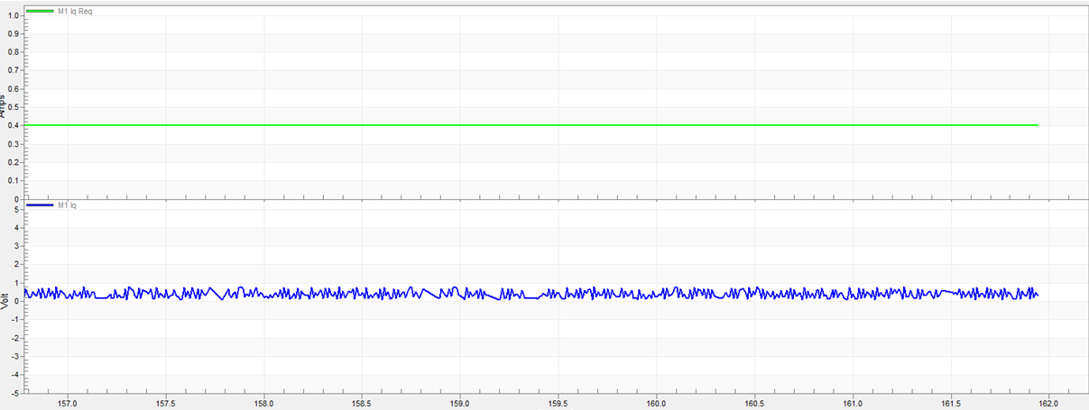
The tuning ensures that the Iq command and Iq feedback are stable:
Tuning Iq command under varying conditions:
6. Speed Loop Tuning
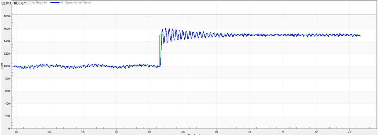
For speed loop tuning, we mainly need to tune the Speed PID controller parameters. By observing the Speed command and feedback values using Freemaster, we can verify the tuning. On the NXP MCX_A motor platform, use speed control mode to check whether the speed feedback follows the command. Use PID tuning techniques to complete the speed loop tuning. Depending on customer requirements, select appropriate parameters to prioritize speed, accept larger overshoot, or achieve stability without oscillation (critical damping). The motor controller requirements vary based on customer applications.
Command 1000 -> 1500 with significant oscillation:
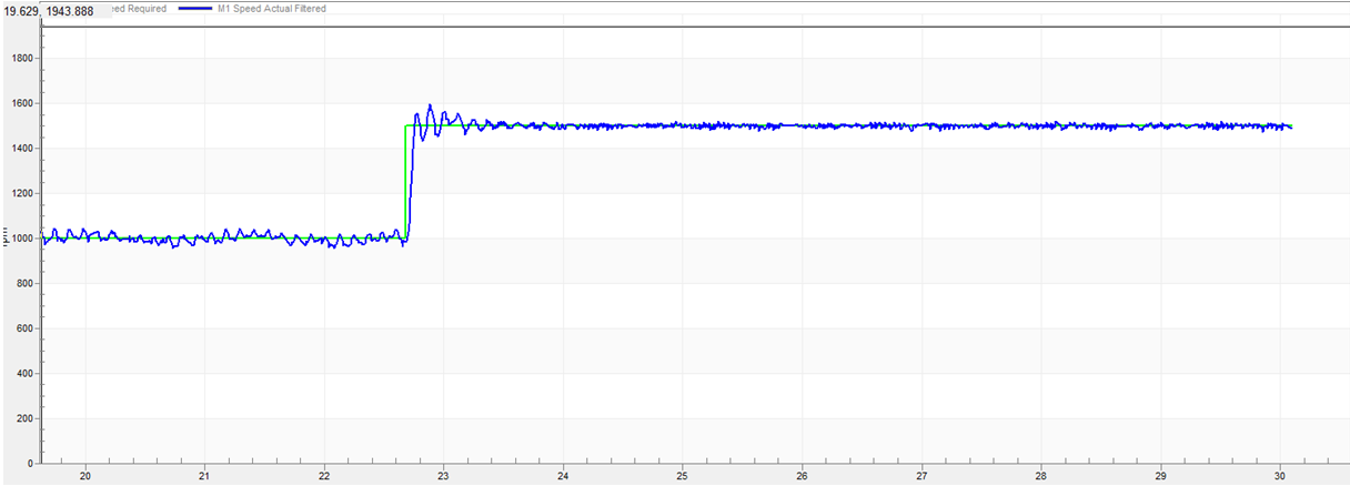
Lower Kp and increase Ki to optimize oscillation issues:
7. Field Weakening Control
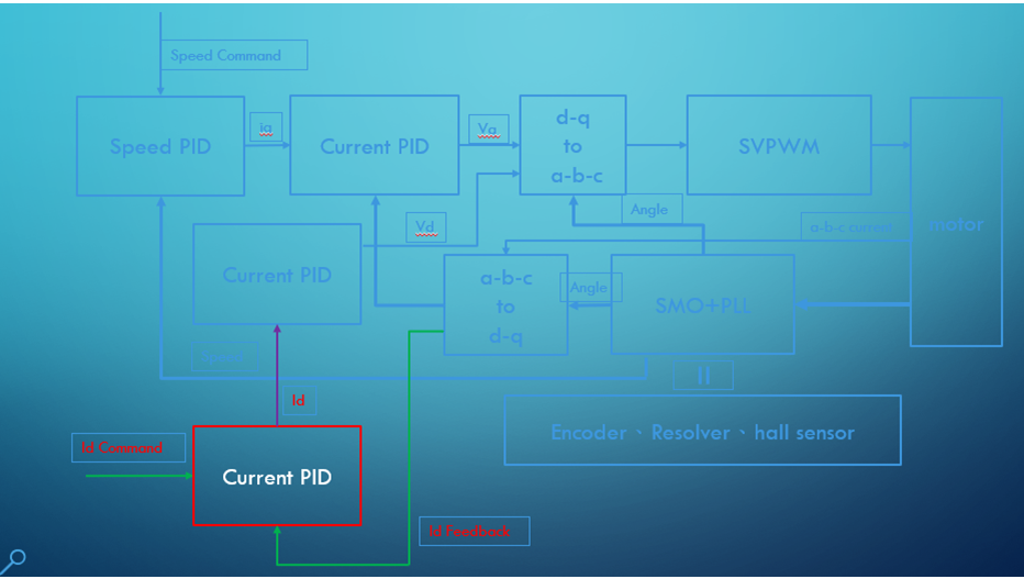
Field weakening control, as described in the diagram below, adds a PID control for Id, setting Id to a negative value. This can be understood as offsetting part of the permanent magnet's magnetic force, allowing the motor to exceed its rated speed. The stronger the motor, the more effective this can be. However, excessive or prolonged field weakening can generate excessive heat, potentially demagnetizing the permanent magnets. Therefore, it is important to monitor whether excessive field weakening causes current consumption to exceed the motor's load capacity, leading to overheating.
8. References