
In today's world, where environmental awareness is on the rise, the automotive industry is undergoing significant changes. Tasks that were once solely reliant on internal combustion engines will, in the future, be handled by vehicles powered by hybrid systems, electric motors, or even fuel cells. In the past, many manufacturers focused on the mechanical components essential for traditional internal combustion engines and transmission systems. Moving forward, the focus will shift to other components. For instance, they may develop new solid-state batteries to increase range and the number of charge/discharge cycles—capabilities that current lithium-ion batteries cannot achieve. They may also prioritize the development of high-performance chargers, DC/DC converters, and electric motors.
As a core component, the Battery Management System (BMS) is responsible for the proper management and monitoring of batteries. Currently, electric vehicles use lithium-ion batteries. These batteries are connected to form a battery pack that achieves the required total voltage. Individual battery cells typically have a voltage of about 3.6V to 3.7V, and high-voltage systems for electric vehicles, such as 520V or 900V, require approximately 140 to 250 cells. In such configurations, it is essential to monitor the temperature, impedance (internal resistance), voltage, and charge/discharge current of the batteries.
 BMS generally includes components such as Cell Monitoring Controllers (CMC) and a main control central unit or Battery Management Controller (BMC). The CMC uses multi-channel ICs (currently supporting up to 16 channels) to perform monitoring functions, while the BMC controls each CMC (Figure 1).
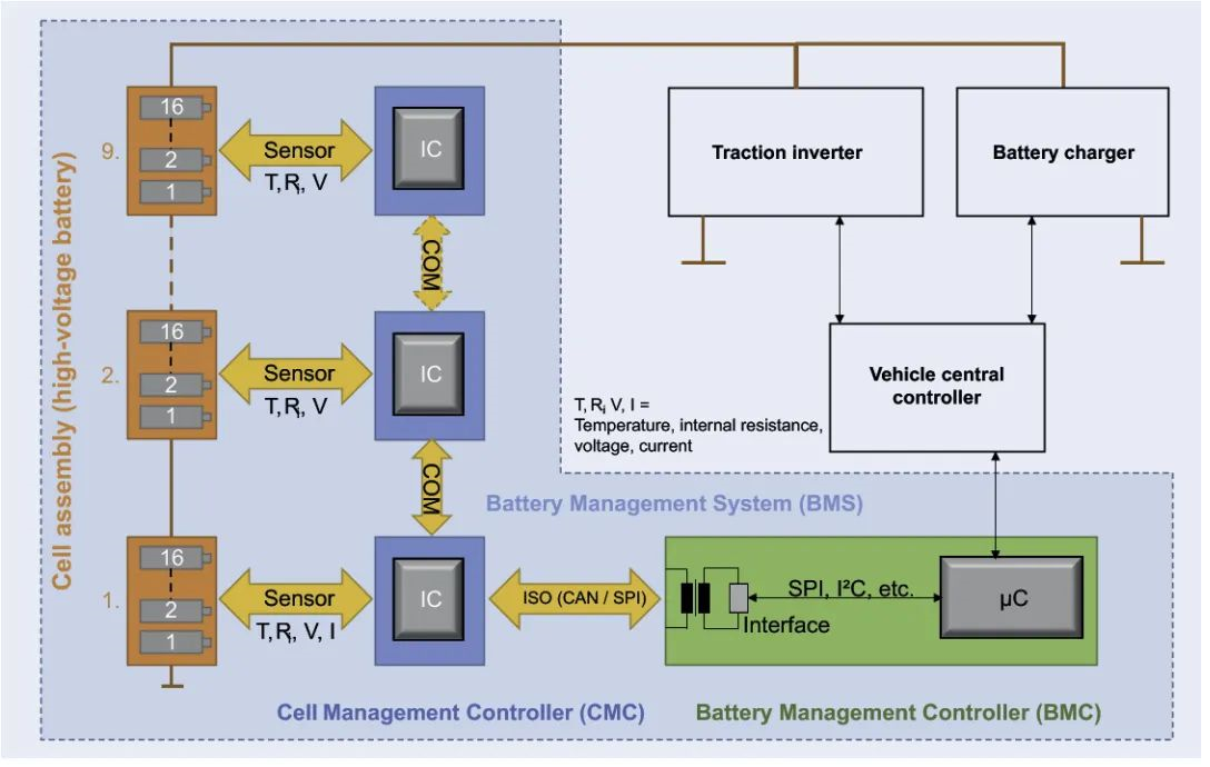 Figure 1: Schematic of an advanced automotive battery management system architecture and interface description
 ### 01 Temperature Monitoring
Typically, NTC thermistors are attached to the battery or module wall, or connected to electrical contacts to measure temperature. As the thermistor's temperature increases, its resistance decreases, improving sensitivity (due to the thermistor's negative temperature coefficient). Temperature can be determined using an integrated analog-to-digital converter (ADC) on a chip by measuring the voltage across the resistor-thermistor network. Accurate temperature readings are critical for the proper functioning of the battery and the safety of the system. The relationship between the NTC and the measurement circuit resistance affects the accuracy of temperature measurements.
### 01 Temperature Monitoring
Typically, NTC thermistors are attached to the battery or module wall, or connected to electrical contacts to measure temperature. As the thermistor's temperature increases, its resistance decreases, improving sensitivity (due to the thermistor's negative temperature coefficient). Temperature can be determined using an integrated analog-to-digital converter (ADC) on a chip by measuring the voltage across the resistor-thermistor network. Accurate temperature readings are critical for the proper functioning of the battery and the safety of the system. The relationship between the NTC and the measurement circuit resistance affects the accuracy of temperature measurements.
Figure 2: LTspice XVII simulation of chip or ADC input resistor/thermistor voltage divider bridge for battery temperature detection
In Figure 2, the NTC can be a single-piece ceramic NTC surface-mount thermistor, such as the NTCS0603E3103FLT (shown in Figure 3), with an R25 value of 10kΩ, ±1%, and a B value of 3435K, ±1%. This device offers superior mechanical bending strength compared to some multilayer devices installed on flexible PCBs (FPCs).
 Figure 3: NTC reference design, technical performance comparison, and NTCAFLEX05 series flexible foil sensor reference design
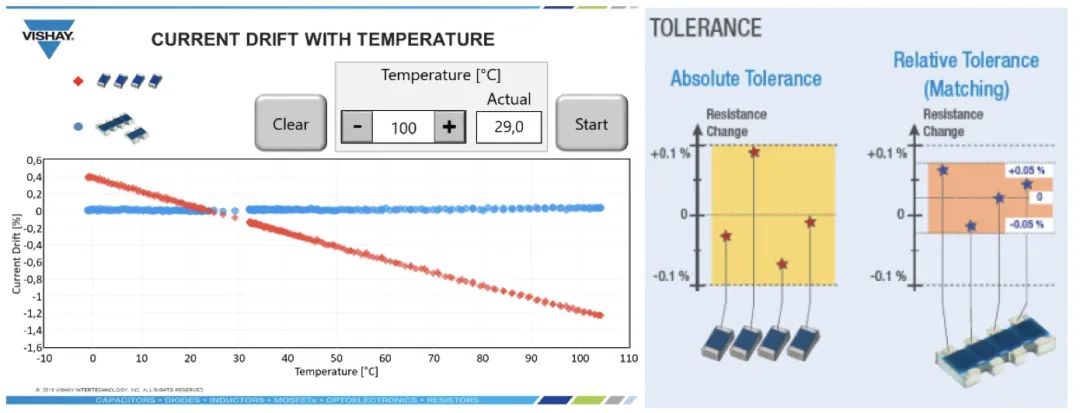
This thermistor also has high thermal cycling resistance and low resistance drift at high temperatures. NTC thermistors can be placed in TNPW/TNPU series fixed resistor networks—these resistors feature ultra-precise tolerances and low temperature coefficients (as low as ±0.1%, ±25 ppm/°C)—or in ACAS network resistors, which support relative tolerances of ±0.05% and absolute tolerances of 0.1% (Figure 4). The control chip samples the voltage generated by the NTC thermistor (Vntc) and detects high and low thresholds.
Figure 3: NTC reference design, technical performance comparison, and NTCAFLEX05 series flexible foil sensor reference design
This thermistor also has high thermal cycling resistance and low resistance drift at high temperatures. NTC thermistors can be placed in TNPW/TNPU series fixed resistor networks—these resistors feature ultra-precise tolerances and low temperature coefficients (as low as ±0.1%, ±25 ppm/°C)—or in ACAS network resistors, which support relative tolerances of ±0.05% and absolute tolerances of 0.1% (Figure 4). The control chip samples the voltage generated by the NTC thermistor (Vntc) and detects high and low thresholds.
 ### 02 Impedance Monitoring
Comprehensive impedance measurements are not required. This method allows for more accurate estimation of the State of Charge (SOC) and State of Health (SOH). Simply put, the method involves applying alternating current at different frequencies. Then, using software-based models, the complex voltage is transformed and analyzed, similar to current.
### 03 Individual Cell Voltage Monitoring
Individual cell voltage is typically measured using an ADC integrated into a chip. This method uses a multiplexer to sequentially measure the voltage of each cell, converting it into digital signals for evaluation.
### 04 Current Monitoring
Current (charging or discharging) is not measured for each cell but for the entire battery pack. This approach is based on the fact that the battery pack is "filled" via a central charger, which can use an onboard charger (OBC) for AC charging or an external charger for DC charging. Since the cells are connected in series, the current is the same for all cells, so the system current only needs to be measured once. Measurement can be performed using Hall-effect current sensors or low-resistance shunt resistors.
### 02 Impedance Monitoring
Comprehensive impedance measurements are not required. This method allows for more accurate estimation of the State of Charge (SOC) and State of Health (SOH). Simply put, the method involves applying alternating current at different frequencies. Then, using software-based models, the complex voltage is transformed and analyzed, similar to current.
### 03 Individual Cell Voltage Monitoring
Individual cell voltage is typically measured using an ADC integrated into a chip. This method uses a multiplexer to sequentially measure the voltage of each cell, converting it into digital signals for evaluation.
### 04 Current Monitoring
Current (charging or discharging) is not measured for each cell but for the entire battery pack. This approach is based on the fact that the battery pack is "filled" via a central charger, which can use an onboard charger (OBC) for AC charging or an external charger for DC charging. Since the cells are connected in series, the current is the same for all cells, so the system current only needs to be measured once. Measurement can be performed using Hall-effect current sensors or low-resistance shunt resistors.
 Another core task of the BMS is balancing each cell. During production, variations in capacity and internal resistance occur due to manufacturing processes. As a result, the battery pack may charge or discharge unevenly. To fully utilize the battery's energy (range), it is necessary to balance the capacity and voltage of each cell. There are two basic principles for charge balancing: active balancing and passive balancing.
### 01 Active Balancing
In active balancing, excess energy from a cell is transferred to an inductor when a field-effect transistor is turned on. When turned off, the energy in the inductor is transferred to the next cell via a diode. This process continues until all cells reach the full charge voltage (Figure 5).
Another core task of the BMS is balancing each cell. During production, variations in capacity and internal resistance occur due to manufacturing processes. As a result, the battery pack may charge or discharge unevenly. To fully utilize the battery's energy (range), it is necessary to balance the capacity and voltage of each cell. There are two basic principles for charge balancing: active balancing and passive balancing.
### 01 Active Balancing
In active balancing, excess energy from a cell is transferred to an inductor when a field-effect transistor is turned on. When turned off, the energy in the inductor is transferred to the next cell via a diode. This process continues until all cells reach the full charge voltage (Figure 5).
 Figure 5: Active balancing schematic
### 02 Passive Balancing
Figure 5: Active balancing schematic
### 02 Passive Balancing
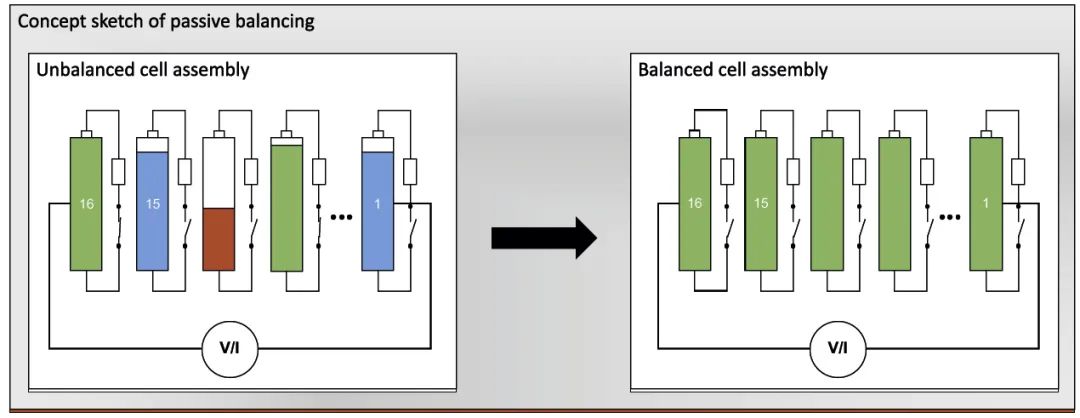 Figure 6: Passive balancing schematic
Vishay offers a significantly different approach. Compared to traditional thick-film resistors, double-coated CRCW-HP resistors and specially trimmed RCS resistors can increase continuous power by two to three times within the same footprint. Additionally, for the same power requirements, these resistor series can reduce the required PCB space, saving costs. Another option is the RCL series resistors, which feature wide terminals for increased continuous power and improved thermal cycling performance. In the automotive industry, where components must operate reliably within a temperature range of -55°C to +125°C and under increased cycling conditions, reliable soldering between components and PCBs is another critical selection criterion. Due to the high cost of active balancing circuits and the narrow manufacturing tolerances for internal resistance and capacitance, passive balancing is predominantly used in the automotive sector.
Figure 6: Passive balancing schematic
Vishay offers a significantly different approach. Compared to traditional thick-film resistors, double-coated CRCW-HP resistors and specially trimmed RCS resistors can increase continuous power by two to three times within the same footprint. Additionally, for the same power requirements, these resistor series can reduce the required PCB space, saving costs. Another option is the RCL series resistors, which feature wide terminals for increased continuous power and improved thermal cycling performance. In the automotive industry, where components must operate reliably within a temperature range of -55°C to +125°C and under increased cycling conditions, reliable soldering between components and PCBs is another critical selection criterion. Due to the high cost of active balancing circuits and the narrow manufacturing tolerances for internal resistance and capacitance, passive balancing is predominantly used in the automotive sector.
 ### 01 Functional Safety (ISO 26262, ASIL-D)
Batteries and their monitoring systems are critical for safety. Therefore, the components used in the system, as well as the system itself, must be developed according to ISO 26262 to meet ASIL-D requirements. As such, BMS with voltage measurement, temperature measurement, and current measurement (excluding internal resistance measurement) functions are as important as systems like airbags, braking systems, and power steering. Failures or defects in these systems directly endanger life and limb.
### 02 Redundant Independent Measurement Methods to Minimize Risk
In this context, monitoring battery voltage is a critical parameter, as overcharging or deep discharging of any cell can cause internal short circuits, leading to thermal runaway during the next charge cycle.
Redundant battery voltage measurement can be achieved using two battery chips. However, this method has the drawback of requiring the same measurement method and being costly. Another solution is to use discharge balancing resistors to measure battery voltage analogously and compare the results with the chip's battery voltage measurements. This is a cost-effective independent measurement method. Thick-film discharge resistors are unsuitable for this measurement. Instead, thin-film resistors should be used, as they ensure precise measurements throughout their lifecycle, even under harsh conditions.
Vishay offers several options for this purpose. First, the MC-HP series resistors, manufactured using special thin-film technology, provide long-term stability (≤0.2%; P70, 1000 hours), doubling the performance of standard thin-film resistors. Second, the MCW series resistors with thin-film technology and wide terminals (sizes 0406 and 0612) meet long-term stability requirements (≤0.2%; P70, 1000 hours) and continuous power-to-space ratio demands, requiring only one-third of the space for nearly the same continuous power (Figure 7). They also improve thermal cycling performance (3000 cycles). With these characteristics, this series of resistors is suitable for use as discharge resistors or battery voltage measurement resistors in BMS, meeting ASIL-D requirements for future systems.
### 01 Functional Safety (ISO 26262, ASIL-D)
Batteries and their monitoring systems are critical for safety. Therefore, the components used in the system, as well as the system itself, must be developed according to ISO 26262 to meet ASIL-D requirements. As such, BMS with voltage measurement, temperature measurement, and current measurement (excluding internal resistance measurement) functions are as important as systems like airbags, braking systems, and power steering. Failures or defects in these systems directly endanger life and limb.
### 02 Redundant Independent Measurement Methods to Minimize Risk
In this context, monitoring battery voltage is a critical parameter, as overcharging or deep discharging of any cell can cause internal short circuits, leading to thermal runaway during the next charge cycle.
Redundant battery voltage measurement can be achieved using two battery chips. However, this method has the drawback of requiring the same measurement method and being costly. Another solution is to use discharge balancing resistors to measure battery voltage analogously and compare the results with the chip's battery voltage measurements. This is a cost-effective independent measurement method. Thick-film discharge resistors are unsuitable for this measurement. Instead, thin-film resistors should be used, as they ensure precise measurements throughout their lifecycle, even under harsh conditions.
Vishay offers several options for this purpose. First, the MC-HP series resistors, manufactured using special thin-film technology, provide long-term stability (≤0.2%; P70, 1000 hours), doubling the performance of standard thin-film resistors. Second, the MCW series resistors with thin-film technology and wide terminals (sizes 0406 and 0612) meet long-term stability requirements (≤0.2%; P70, 1000 hours) and continuous power-to-space ratio demands, requiring only one-third of the space for nearly the same continuous power (Figure 7). They also improve thermal cycling performance (3000 cycles). With these characteristics, this series of resistors is suitable for use as discharge resistors or battery voltage measurement resistors in BMS, meeting ASIL-D requirements for future systems.
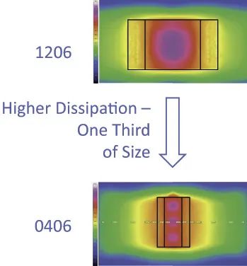 Figure 7: Thermal comparison of high-performance wide-terminal thin-film resistors, requiring one-third the space of conventional terminals
As performance, space requirements, estimated lifespan, and parameter drift demands increase, and safety regulations become stricter, it is impossible to select components—especially for electric drivetrain systems—without a deep understanding of the entire system design. In this regard, Vishay offers a wide range of differentiated products and solutions that contribute to the efficient and safe design of the entire system.
Figure 7: Thermal comparison of high-performance wide-terminal thin-film resistors, requiring one-third the space of conventional terminals
As performance, space requirements, estimated lifespan, and parameter drift demands increase, and safety regulations become stricter, it is impossible to select components—especially for electric drivetrain systems—without a deep understanding of the entire system design. In this regard, Vishay offers a wide range of differentiated products and solutions that contribute to the efficient and safe design of the entire system.
BMS generally includes components such as Cell Monitoring Controllers (CMC) and a main control central unit or Battery Management Controller (BMC). The CMC uses multi-channel ICs (currently supporting up to 16 channels) to perform monitoring functions, while the BMC controls each CMC (Figure 1).
Figure 1: Schematic of an advanced automotive battery management system architecture and interface description
### 01 Temperature Monitoring
Typically, NTC thermistors are attached to the battery or module wall, or connected to electrical contacts to measure temperature. As the thermistor's temperature increases, its resistance decreases, improving sensitivity (due to the thermistor's negative temperature coefficient). Temperature can be determined using an integrated analog-to-digital converter (ADC) on a chip by measuring the voltage across the resistor-thermistor network. Accurate temperature readings are critical for the proper functioning of the battery and the safety of the system. The relationship between the NTC and the measurement circuit resistance affects the accuracy of temperature measurements.


Figure 3: NTC reference design, technical performance comparison, and NTCAFLEX05 series flexible foil sensor reference design
This thermistor also has high thermal cycling resistance and low resistance drift at high temperatures. NTC thermistors can be placed in TNPW/TNPU series fixed resistor networks—these resistors feature ultra-precise tolerances and low temperature coefficients (as low as ±0.1%, ±25 ppm/°C)—or in ACAS network resistors, which support relative tolerances of ±0.05% and absolute tolerances of 0.1% (Figure 4). The control chip samples the voltage generated by the NTC thermistor (Vntc) and detects high and low thresholds.
### 02 Impedance Monitoring
Comprehensive impedance measurements are not required. This method allows for more accurate estimation of the State of Charge (SOC) and State of Health (SOH). Simply put, the method involves applying alternating current at different frequencies. Then, using software-based models, the complex voltage is transformed and analyzed, similar to current.
### 03 Individual Cell Voltage Monitoring
Individual cell voltage is typically measured using an ADC integrated into a chip. This method uses a multiplexer to sequentially measure the voltage of each cell, converting it into digital signals for evaluation.
### 04 Current Monitoring
Current (charging or discharging) is not measured for each cell but for the entire battery pack. This approach is based on the fact that the battery pack is "filled" via a central charger, which can use an onboard charger (OBC) for AC charging or an external charger for DC charging. Since the cells are connected in series, the current is the same for all cells, so the system current only needs to be measured once. Measurement can be performed using Hall-effect current sensors or low-resistance shunt resistors.
Another core task of the BMS is balancing each cell. During production, variations in capacity and internal resistance occur due to manufacturing processes. As a result, the battery pack may charge or discharge unevenly. To fully utilize the battery's energy (range), it is necessary to balance the capacity and voltage of each cell. There are two basic principles for charge balancing: active balancing and passive balancing.
### 01 Active Balancing
In active balancing, excess energy from a cell is transferred to an inductor when a field-effect transistor is turned on. When turned off, the energy in the inductor is transferred to the next cell via a diode. This process continues until all cells reach the full charge voltage (Figure 5).
Figure 5: Active balancing schematic
### 02 Passive Balancing
Figure 6: Passive balancing schematic
Vishay offers a significantly different approach. Compared to traditional thick-film resistors, double-coated CRCW-HP resistors and specially trimmed RCS resistors can increase continuous power by two to three times within the same footprint. Additionally, for the same power requirements, these resistor series can reduce the required PCB space, saving costs. Another option is the RCL series resistors, which feature wide terminals for increased continuous power and improved thermal cycling performance. In the automotive industry, where components must operate reliably within a temperature range of -55°C to +125°C and under increased cycling conditions, reliable soldering between components and PCBs is another critical selection criterion. Due to the high cost of active balancing circuits and the narrow manufacturing tolerances for internal resistance and capacitance, passive balancing is predominantly used in the automotive sector.
### 01 Functional Safety (ISO 26262, ASIL-D)
Batteries and their monitoring systems are critical for safety. Therefore, the components used in the system, as well as the system itself, must be developed according to ISO 26262 to meet ASIL-D requirements. As such, BMS with voltage measurement, temperature measurement, and current measurement (excluding internal resistance measurement) functions are as important as systems like airbags, braking systems, and power steering. Failures or defects in these systems directly endanger life and limb.
### 02 Redundant Independent Measurement Methods to Minimize Risk
In this context, monitoring battery voltage is a critical parameter, as overcharging or deep discharging of any cell can cause internal short circuits, leading to thermal runaway during the next charge cycle.
Redundant battery voltage measurement can be achieved using two battery chips. However, this method has the drawback of requiring the same measurement method and being costly. Another solution is to use discharge balancing resistors to measure battery voltage analogously and compare the results with the chip's battery voltage measurements. This is a cost-effective independent measurement method. Thick-film discharge resistors are unsuitable for this measurement. Instead, thin-film resistors should be used, as they ensure precise measurements throughout their lifecycle, even under harsh conditions.
Vishay offers several options for this purpose. First, the MC-HP series resistors, manufactured using special thin-film technology, provide long-term stability (≤0.2%; P70, 1000 hours), doubling the performance of standard thin-film resistors. Second, the MCW series resistors with thin-film technology and wide terminals (sizes 0406 and 0612) meet long-term stability requirements (≤0.2%; P70, 1000 hours) and continuous power-to-space ratio demands, requiring only one-third of the space for nearly the same continuous power (Figure 7). They also improve thermal cycling performance (3000 cycles). With these characteristics, this series of resistors is suitable for use as discharge resistors or battery voltage measurement resistors in BMS, meeting ASIL-D requirements for future systems.
Figure 7: Thermal comparison of high-performance wide-terminal thin-film resistors, requiring one-third the space of conventional terminals
As performance, space requirements, estimated lifespan, and parameter drift demands increase, and safety regulations become stricter, it is impossible to select components—especially for electric drivetrain systems—without a deep understanding of the entire system design. In this regard, Vishay offers a wide range of differentiated products and solutions that contribute to the efficient and safe design of the entire system.