
1. Introduction
For customer engineers, it is often necessary to consider the thermal characteristics of devices in actual projects and to prepare corresponding thermal impedance reports to build thermal simulation models.
This note primarily addresses questions raised by customer engineers regarding the thermal characteristics of Micron products during thermal simulations.
The functionality and reliability of Micron storage products are primarily determined by junction temperature. The maximum junction temperature table provides an overview of the junction temperature limits for product families. Each device must operate below the defined junction temperature to ensure functionality and long-term reliability.
2. Key Parameters for Thermal Simulation
For thermal simulation, the above diagram shows a commonly used thermal resistance parameter model for devices. In this model, TA represents the ambient air temperature, TB represents the PCB temperature, and TC represents the temperature of the chip package's outer shell. For engineers conducting thermal simulations, there are several key indicators to focus on:
Junction Temperature (TJ)
In the diagram above, the junction temperature is represented as TJ, which refers to the temperature of the active region inside the device. This temperature is critical because it directly affects the device's functionality and reliability. TJ represents the maximum rated temperature defined by Micron. Exceeding this temperature may cause the device to malfunction. Prolonged exposure to the absolute maximum rated temperature may impact reliability due to the device and packaging.
In practical applications, the junction temperature can be estimated by measuring the case temperature (Tc) and combining it with the thermal resistance from the junction to the case (θjc). For example, if the case temperature is known to be 74°C, the power passing through the case is 100%, and the thermal resistance is 7°C/W, the junction temperature can be calculated using the formula Tj = Tc + (Pc × θjc), where Pc is the power passing through the case. If the proportion of power passing through the case changes, the junction temperature will also vary.
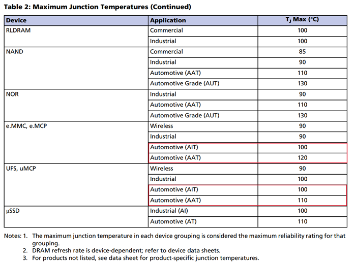
The following diagram shows some commonly used TJ rated temperature tables:
Thermal Resistance (θ)
Thermal resistance is a measure of the ability to transfer heat between two points, typically denoted by the symbol θ. There are several types of thermal resistance, such as junction-to-ambient (θJA), junction-to-case (θJC), and junction-to-board (θJB).
For Micron memory chips, each package and DID has a corresponding thermal resistance value.
3. How to Obtain Thermal Simulation Models and Parameters
First, confirm the specific part number you need to query and contact the corresponding FAE. Micron will retrieve the information from the system and provide it to the customer.
It is important to note that thermal models are independent of the temperature grade of the part number. The same model can be applied to WT/IT/AT/UT temperature grades.
4. Conclusion
In summary, thermal management is critical to ensuring the reliability and functionality of semiconductor products such as memory components. Junction temperature, as a key indicator of the internal temperature of semiconductor devices, must be maintained within the specified range to ensure proper operation. Micron provides detailed numerical references by defining clear thermal resistance parameters, junction temperature limits, and offering comprehensive modeling and simulation guidelines. For further information, you can contact the corresponding FAE engineer to obtain the necessary data.
5. References
[1] Micron: TN-00-08: Thermal Applications Device Thermal Information