Thermal management in data centers has always been a challenging requirement for design engineers. Today, advanced applications such as Artificial Intelligence (AI) and Machine Learning are pushing high data processing demands to a new level, making traditional I/O module cooling solutions potentially insufficient. It is imperative to reassess whether existing thermal management systems can meet the requirements of system upgrades and to develop new thermal management solutions urgently.
Emerging Thermal Technology Advancements in the Data Center Ecosystem
Cloud computing in data centers has become a major driver of digital products and services, ranging from basic email to complex generative AI. This computing power is not free; every server in a data center requires electricity to operate. Power consumption can reach significant levels, especially in data centers supporting high data processing demands in advanced fields like AI and machine learning. Thermal management is one of the primary costs of operating a data center, and effective thermal management reduces long-term maintenance costs by extending component lifespans. Current liquid cooling systems can cost up to $2,000 per kW of cooling power, and enterprise data center cooling system investments can easily exceed $100,000.
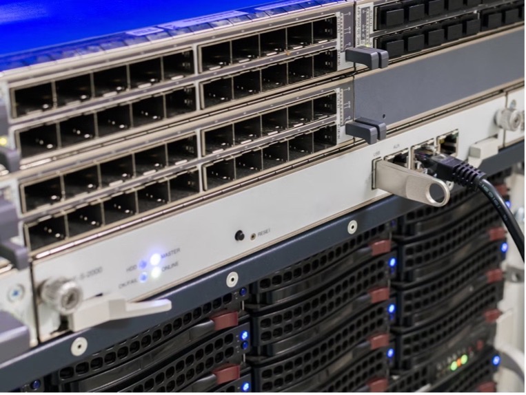
At today’s 112 Gbps-PAM4 data rates, power levels range from approximately 15W to 25W. Optical I/O modules in large enterprise switches with just 32 ports can consume up to 0.8kW of power. For long-distance 112G communication using coherent (800G) optical devices, the power level per module can reach up to 30W.
The transition to next-generation 224 Gbps-PAM4 interconnects means doubling the data rate per channel. Power consumption will also increase, with optical modules in long-distance coherent links reaching up to 40W. This is challenging because the power requirements for optical I/O modules have increased from 12W to 40W in just a few years, while the module form factor has remained unchanged. This essentially means a nearly fourfold increase in power density, necessitating new cooling methods.
Current Active Cooling Methods
Forced Air Cooling: Air cooling is a low-risk active cooling method. When the power demand per rack is around 10kW, forced ventilation systems can typically handle the thermal load.
Direct-to-Chip Liquid Cooling: One liquid cooling option for data centers is direct-to-chip liquid cooling. When rack power demands reach 25kW to 50kW, direct-to-chip cooling is required to provide heat dissipation.
Enhanced Passive Components for Active Cooling: Some passive components assist active cooling strategies by aiding heat transfer and providing additional thermal quality. Common passive components include heat sinks and heat pipes.
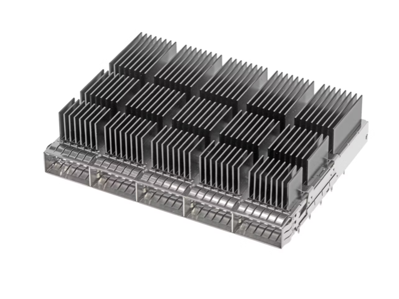
QSFP-DD housing with heat sink
Immersion Cooling
The most efficient liquid cooling option in data centers is immersion cooling, but it comes with significant risks and costs:
-
Investment: The equipment and installation costs of immersion cooling systems can be more expensive than forced air or liquid cooling.
-
Space Requirements: Immersion cooling tank racks are wider and deeper than standard rack units.
-
Compatible I/O Modules and Connectors: The dielectric constant of the fluid affects connector impedance, requiring special connectors and transceiver modules.
-
Compatible Servers: Servers used with immersion cooling are specially built.
-
Fluid: Immersion cooling fluids require specialized circulation systems for cooling.
-
Maintenance: Immersion cooling systems incur high maintenance costs.
-
Leakage Risk: Catastrophic leaks in immersion cooling systems can damage facilities.
-
Component Failure: Insufficient fluid flow can lead to high temperatures, accelerating aging and causing early failures.
-
Environmental Impact: Fluids used in immersion cooling require periodic replacement.
Thermal Challenges of Optical I/O Modules
Optical I/O modules within server and rack-mounted network infrastructure systems always receive direct cooling from active cooling systems. Optimizing cooling strategies to account for processor cooling needs and overall optical I/O module power helps improve system power efficiency.
Link Length and Data Rate: 56G and 112G optical I/O modules are currently cooled using air. At data rates of 112G or higher, pluggable optical I/O modules with power levels of 33W+ require liquid cooling measures to be extended to the modules.
Form Factor: The form factor has not changed since optical transceiver modules were implemented 20 years ago. New-generation optical I/O modules need to be backward compatible with existing rack-mounted equipment, meaning thermal density will increase, leading to insufficient forced airflow for cooling optical I/O modules.
Heat Dissipation: Heat sinks connected to optical I/O modules rely on metal-to-metal contact to maximize heat transfer. Bare metal contact is undesirable for any heat sink interface. To improve the thermal contact resistance of the contact surface, thermal interface materials (TIM) are installed on riding heat sinks to enhance heat transfer efficiency.
Monitoring Module Temperature: Increasing power density requires reevaluating traditional thermal characterization methods for optical modules. Traditionally, a 70°C case temperature requirement is used as the thermal specification (representing the Digital Optical Monitoring (DOM) temperature).
Module temperature illustration
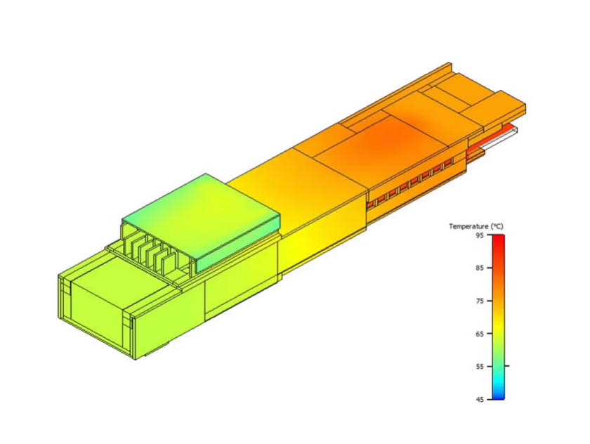
Simulation and Testing: Simulation/predictive engineering is used to optimize system design, component placement, and cooling strategies before construction and deployment. Optimizing forced air approaches on heat sinks and optical modules often requires simulating airflow across the entire chassis before finalizing mechanical designs.
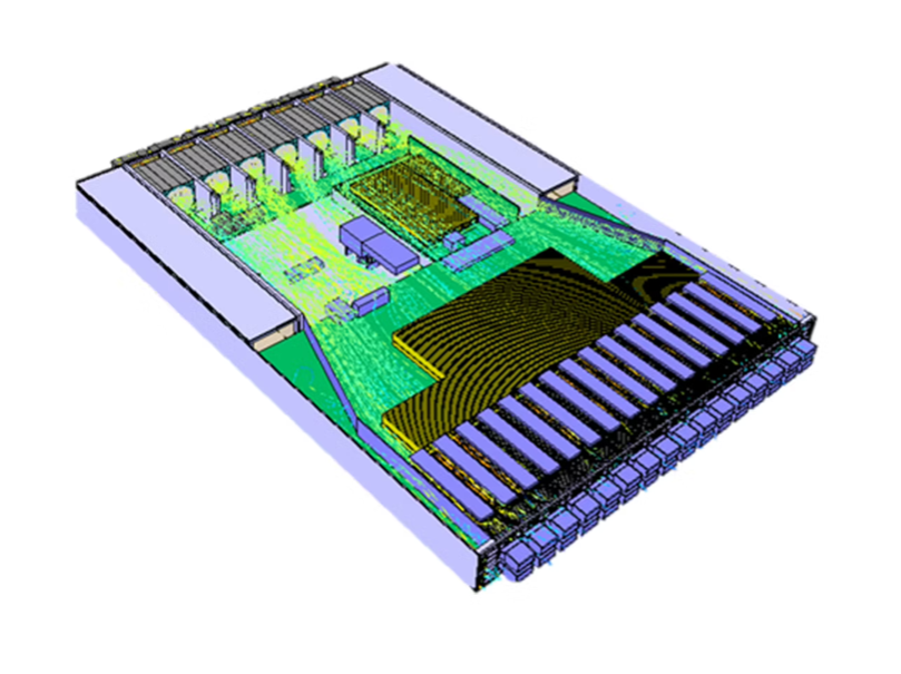 Thermal simulation system
Immersion Cooling: 112G and 224G optical modules can be cooled in immersion cooling systems.
Innovative Thermal Management Solutions for Data Center Architectures
Given the increasing thermal loads and the form factor constraints caused by backward compatibility of servers and optical I/O modules, existing liquid cooling solutions in servers and switches may need to be extended to modules to support higher data rates and computational demands in data centers. Specifically for I/O, new solutions can be integrated into servers and switches to provide greater heat dissipation without compromising reliability. This is achieved through mechanical modifications directly on the modules and innovative liquid cooling, maintaining the standard form factor used in rack-mounted network systems and pluggable modules.
Molex Advanced Thermal I/O Solutions
Molex’s Drop-Down Heat Sink (DDHS)
Compared to traditional heat sinks, the DDHS solution provides a +9°C improvement in thermal performance. This innovation enables effective air cooling solutions for over 30W, reducing the need for more expensive liquid cooling alternatives while maintaining system durability and performance.
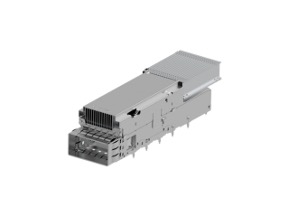
Molex’s Drop-Down Heat Sink System
System designers can leverage Molex’s DDHS solution to achieve a 9°C improvement in one of two ways:
-
Using modules with the same power (e.g., 30W), simply reduce system fan speeds to utilize the thermal margin of the DDHS, achieving higher energy efficiency.
-
Cool higher-power modules (35-37W instead of 30W) while running fans at the same speed.
Advanced Liquid Cooling Solutions
Molex has developed a liquid cooling solution called the Integrated Floating Base. Each base in contact with the module is spring-tuned and independently movable, allowing a single cold plate to be implemented in various 1xN and 2xN single-row and stacked cage configurations. The independently movable bases compensate for different tolerance stacks at each port while still providing the required downward pressure for good thermal contact.
The 1x6 QSFP-DD liquid cooling solution shown below features six independently movable bases that compensate for different stacks at each port while ensuring good thermal contact (with the required downward pressure).
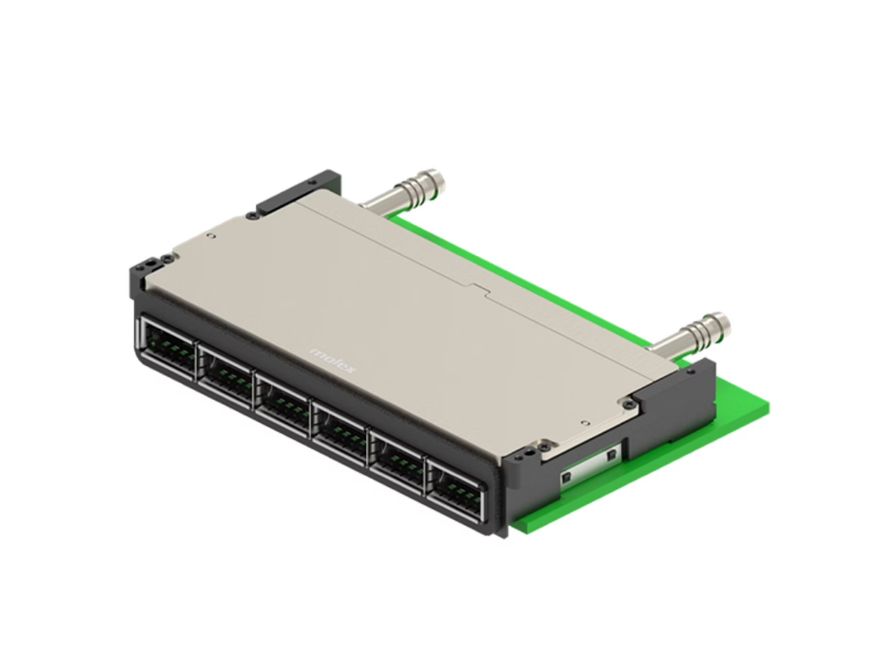
Molex’s Integrated Floating Base Example
This integrated floating base enables I/O liquid cooling without thermal or mechanical fillers. Heat flows directly from the module to the base, which is directly connected to the liquid flowing through the cold plate. This minimizes thermal resistance and improves heat transfer efficiency.
Molex has demonstrated that using this liquid cooling solution, modules up to 40W can be cooled within specification ranges.
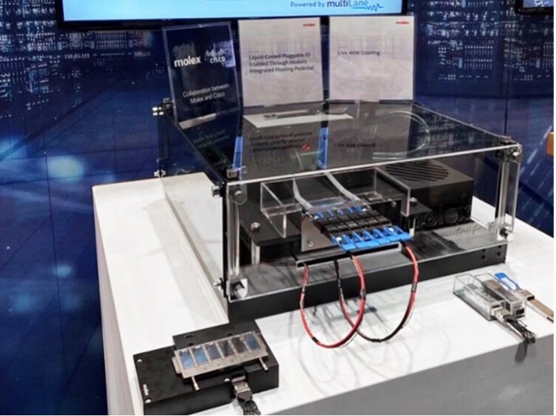
Molex Liquid Cooling Solution Demonstration
Standardization and Testing of Next-Generation Cooling Strategies
Cooling designs for optical modules are generally influenced by using case temperature as the module temperature specification or limit. However, case temperature specifications cannot accurately reflect the internal temperature of critical components within the module. The temperature limits of internal components are the true limiting specifications for module temperature.
The traditional method of monitoring module temperature involves selecting a monitoring point on the module case, which may be located under the heat sink. However, during operation, it is often impossible to detect this monitoring point without interfering with the heat sink. Therefore, it is recommended to use a software management interface (e.g., CMIS) to read the Tcase value detected by internal sensors via Digital Optical Monitoring (DOM).
The table below shows the margin differences calculated using case temperature and the actual temperature of critical internal components:
Module
|
Limits
|
Actual
|
Margin (ΔT)
|
Tcase (above DSP)
|
75°C
|
72.6°C
|
2.4°C
|
Laser
|
85°C
|
76.4°C
|
8.6°C
|
TIA/driver
|
105°C
|
81.4°C
|
23.6°C
|
DSP
|
105°C
|
93.5°C
|
11.5°C
|
Based on the data, cooling strategies can be redesigned to reduce the load on fans, allowing the case temperature to run hotter and enabling the system to utilize some additional margin. Using the module case temperature as the module’s temperature limit yields only a 2.4°C margin. Conversely, if the laser is used as the critical component defining the temperature limit (with the smallest thermal margin), it is found that there is actually 8.6°C of available margin before any performance impact on the laser is observed.
Therefore, it is recommended to redefine the module DOM readings based on the lowest temperature margin of internal components, as shown in the formula below. Additional margin can be utilized in cooling system designs while maintaining backward compatibility with existing CMIS and system software. The value reported in the DOM register becomes:
DOM = 75°C - Min(ΔT(Laser), ΔT(DSP), ΔT(TIA))
This proposed DOM definition has a simple explanation: the DOM value, as well as the actual temperature margin, should be based on the internal component with the smallest margin in the module operating environment (e.g., laser, optics, TIA, DSP chip, etc.). This simple change to the reported DOM value helps system designers eliminate excess margin in cooling system architectures and provides better module control for system management.
★All content is provided by individuals and is unrelated to the platform. For any legal or infringement issues, please contact the Tech Highlights Exclusive Email
