
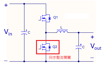
The Buck Converter is one of the most commonly used power conversion architectures, offering advantages such as high efficiency, low cost, and simple design, making it widely applicable. Its applications range from products under 1 W to those exceeding kW. The circuit architecture of a Buck Converter is shown in Figure 1 below. Due to its minimal components and simple control (only requiring control of Q1), it can meet the needs of many low-power applications. However, in applications with higher currents, the diode (D1) introduces a significant forward voltage drop (VF), which poses challenges in terms of efficiency and heat dissipation that engineers must address. The use of MOSFETs to replace diodes in synchronous rectification technology is the optimal solution, as shown in Figure 2 below. Most Buck Converter Control ICs on the market today include synchronous rectification functionality. Although synchronous rectification Buck Converters appear to be ideal, there are still some issues to consider depending on the control method used. The following discussion will cover common control methods for synchronous rectification Buck Converters and the design considerations engineers should take into account when designing products.
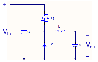
Figure 1. Buck Converter
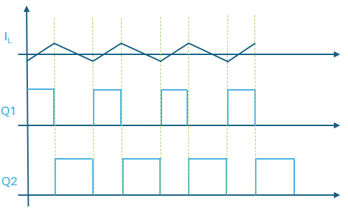
Most synchronous rectification control methods for Buck Converters on the market adopt a fixed-frequency, complementary upper and lower switch control approach. In this mode, the switching frequency remains constant and does not change with the load. This method primarily uses PWM control, which is simple and meets the requirements of most applications. The advantages and disadvantages are as follows:
Advantages:
1. High stability: Since the switching frequency is fixed, the output voltage remains stable, and the duty cycle changes minimally from no load to full load.
2. Simple control: The control circuit design is straightforward and easy to implement.
Disadvantages:
1. Low efficiency under light loads: Under light load conditions, fixed-frequency operation results in higher switching losses, reducing efficiency. Figure 3 below shows the waveform during light load operation.
Since the synchronous rectification Buck Converter architecture can also function as a bidirectional power conversion architecture, as shown in Figure 2, it can convert from Vin to Vout as a Buck Converter or from Vout to Vin as a Boost Converter. This situation may occur in scenarios such as OVP (Over Voltage Protection) testing: when an external voltage is applied to simulate OVP conditions, this architecture can act as a Boost Converter, boosting the voltage at the Vout terminal to the Vin terminal. If the Vin terminal is powered by another switching converter, it may cause OVP or overvoltage damage.
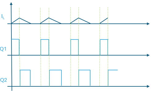
Another synchronous rectification control method involves detecting the inductor current. When the inductor current approaches 0A, the synchronous rectification MOSFET is turned off. This control method makes the behavior of the synchronous rectification MOSFET's conduction and shutdown similar to that of a diode. The light load operation waveform is shown in Figure 4 below. This mode, combined with frequency reduction under light loads, can improve light load efficiency and prevent reverse Boost operation issues when an external voltage source is applied to the Vout terminal, causing the output voltage to exceed the control voltage. The drawback is that the PWM control mechanism is more complex.
3. Introduction to JOULWATT JWH6344 Synchronous Step-Down PWM Controller
The JWH6344 is a synchronous rectification control IC that supports an input voltage range of 6V to 65V and an output voltage range of 0.8V to 55V. It offers two operation modes: FCC mode and PFM mode, which can be configured. The FCC mode synchronous rectification operates in a complementary, fixed-frequency mode as described above, while the PFM mode synchronous rectification operates in a frequency-reduction mode under light loads, as described above. Users can select the appropriate mode based on their specifications and application requirements. Additionally, the IC features enable control (to turn the IC ON/OFF), a power good indicator, and a configurable switching frequency range of 100kHz to 1MHz. Protection features include OTP, OCP, SCP, and Vcc UVP. The IC is packaged in a QFN3.5X4.5-20, providing a compact solution with minimal external components, making it suitable for various non-isolated step-down applications.