
1. Introduction
When the Safety system encounters a panic, developers need to trace and analyze the root cause of the issue. A safety panic tracing tool can help developers quickly locate the problem and perform troubleshooting and debugging.
This article mainly discusses the basic knowledge of Safety panic and the implementation of a tracing tool that can track the function call stack during a panic. By analyzing the stack, developers can trace and locate the flow of code execution that caused the deadlock.
2. CPU Operating States of Arm Processors
The instruction length of Arm microprocessors is 32 bits, but it can also be 16 bits (in Thumb state). Arm microprocessors support three data types: byte (8 bits), halfword (16 bits), and word (32 bits). Words require 4-byte alignment, and halfwords require 2-byte alignment. The CPU operating states of the Arm architecture are as follows:
1. ARM State: The processor executes 32-bit word-aligned ARM instructions.
In ARM state, the processor can access 32-bit data and address spaces simultaneously, providing high-performance computation and storage capabilities. ARM state instructions are 32 bits long and can execute any 32-bit instruction, offering better code efficiency and execution speed.
In ARM state, the processor can execute the following types of instructions:
(1) Data processing instructions: such as addition, subtraction, multiplication, division, and logical operations;
(2) Branch instructions: such as B, BL, and BX, used for jumps and subroutine calls;
(3) Memory access instructions: such as LDR, STR, LDM, and STM, used for reading and writing data and memory;
(4) Other instructions: such as exception handling instructions and coprocessor access instructions.
The ARM instruction set is efficient and flexible, meeting the needs of most embedded applications. However, due to the longer instruction length, it consumes more storage space and puts some pressure on the memory system, leading to increased power consumption.
Advantages:
Performance: Due to the richer instruction set, ARM state instructions typically execute more efficiently, making them suitable for high-performance computing scenarios.
Functionality: Supports more registers and more complex instructions, suitable for complex mathematical operations and data processing.
Applicable Scenarios:
High-performance applications: such as graphics processing, video encoding/decoding, and scientific computing.
Operating system kernels: scenarios requiring frequent context switching and system calls.
Embedded systems: embedded applications requiring complex task handling.
2. Thumb State: The processor executes 16-bit halfword-aligned Thumb instructions.
Thumb state supports a 16-bit instruction set, offering higher code density and lower power consumption. In Thumb state, instructions are 16 bits long, requiring two instructions to access 32-bit data and address spaces. However, this results in smaller program code size, saving memory space and improving cache utilization.
The Thumb instruction set is designed to optimize code density and power efficiency, making it suitable for embedded systems with specific requirements for code size and power consumption. In Thumb state, the processor can execute two types of instructions: Thumb-1 and Thumb-2.
Thumb-1 instructions are 16-bit and provide basic data processing and flow control operations, including arithmetic operations, logical operations, conditional branching, and jumps. Thumb-2 instructions, on the other hand, are 32-bit and can perform advanced data processing and memory access operations. They also support more complex program control structures, such as loops and function calls. Additionally, Thumb-2 instructions can utilize more powerful 32-bit data registers, improving data processing performance.
Advantages:
Code density: Due to shorter instructions, Thumb state code typically occupies less memory, making it suitable for devices with limited memory.
Power consumption: Smaller code size and higher instruction density usually result in lower power consumption, making it ideal for battery-powered devices.
Applicable Scenarios:
Resource-constrained embedded systems: such as sensors and microcontrollers with limited memory and storage space.
Low-power applications: such as portable devices and IoT devices requiring energy efficiency while maintaining performance.
Simple control logic: such as state machines and control algorithms.
In summary, the fundamental difference between ARM and Thumb states lies in the instruction width: ARM uses 32-bit instructions, while Thumb uses 16-bit instructions. Thumb-2 is a combination and optimization of ARM and Thumb states.
The Bx Rn instruction is used to switch between the two states. Bx is a branch instruction, and Rn is a register (1 word, 32 bits). If the least significant bit (LSB) of Rn is 1, the processor switches to Thumb state; if the LSB is 0, it switches to ARM state. (Reason: The last two bits of ARM instructions are always 0 and unused, while the last bit of Thumb instructions is always 0 and unused. Therefore, the LSB is used as the flag for switching between ARM and Thumb instructions.)
3. Switching between ARM and Thumb states does not affect the processor's operating mode or the contents of its registers.
4. When handling exceptions, the ARM processor always switches to ARM state, regardless of its current state.
3. CPU Operating Modes of Arm Processors
The CPU operating modes of the Arm architecture include seven modes: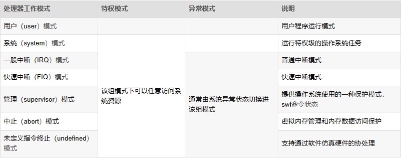
1. User Mode (Usr): User mode is the working mode for user programs. It operates in the user space of the operating system, with no permission to access other hardware resources. It can only process its own data and cannot switch to other modes. To access hardware resources or switch modes, it must use software interrupts or trigger exceptions.
2. Fast Interrupt Mode (FIQ): Fast interrupt mode is used for handling time-critical interrupt requests, primarily for high-speed data transfer and channel processing.
3. Interrupt Mode (IRQ): Used for handling general interrupt requests. The processor automatically enters this mode when a hardware interrupt signal is generated. This mode is a privileged mode, allowing unrestricted access to system hardware resources.
4. Supervisor Mode (SVC): Supervisor mode is the default mode after the CPU powers on. It is mainly used for system initialization and software interrupt handling. When a user program in user mode requests access to hardware resources, it enters this mode via a software interrupt.
Note: The system enters SVC mode during system boot or software interrupts.
5. Abort Mode (ABT): Entered when data or instruction prefetch is aborted. It is used for virtual memory and memory protection. When a user program accesses an illegal address or unauthorized memory, it enters this mode.
6. System Mode (SYS): System mode is a privileged mode not restricted by user mode. User mode and system mode share the same set of registers. In this mode, the operating system can easily access user mode registers, and privileged tasks can access controlled resources.
Note: User mode and system mode share the same registers and lack an SPSR (Saved Program Status Register). However, system mode has higher privileges than user mode, allowing access to all system resources.
7. Undefined Mode (UND): Undefined mode is used for software emulation of hardware coprocessors. When the CPU cannot decode an instruction during the instruction decode phase, it enters undefined mode.
The CPU mode can be understood as the current working state of the CPU. For example, when the operating system is executing a user program, the CPU operates in user mode. If a network card receives data and generates an interrupt signal, the CPU automatically switches to interrupt mode to process the network data (since regular applications cannot directly access hardware). After processing the network data, the CPU returns to user mode to continue executing the user program.
Except for user mode, all other modes are privileged modes. ARM internal registers and some on-chip peripherals are designed to allow access only in privileged modes. Additionally, privileged modes can freely switch processor modes, while user mode cannot directly switch to other modes. Privileged modes are used to handle interrupts, exceptions, or access protected system resources.
Privileged modes, except for system mode, are collectively referred to as exception modes. These modes can be entered either through privileged programs or specific exceptions. For example, hardware interrupt signals trigger interrupt exception mode, unauthorized data access triggers abort exception mode, and executing undefined instructions triggers undefined exception mode. Supervisor mode, also known as superuser mode, is a unique mode for operating systems to handle software interrupts. Software interrupts allow user programs to switch to supervisor mode via system calls.
Hardware privilege levels: System mode > Exception modes > User mode
Exception priority: Reset > Data Abort > FIQ > IRQ > Prefetch Abort > Undefined Instruction > SWI
Exceptions are categorized into synchronous and asynchronous exceptions. Synchronous exceptions are directly caused by the execution of a specific instruction. The processor must handle the exception in the exception handler before continuing execution. For example, during a data abort, the address causing the exception is known, and the exception handler modifies this address. Asynchronous exceptions, on the other hand, are unrelated to the currently executing instruction. For example, interrupts are asynchronous exceptions.
4. Exception Handling Flow
The following is a flowchart of the exception handling process: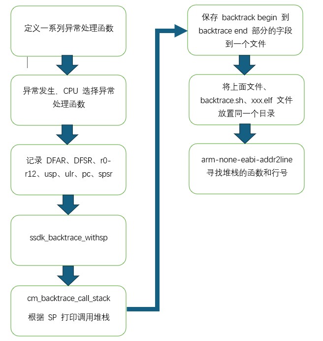
5. Reference Documents
1. "G9_Processor_TRM_Rev01.01"
6. Conclusion
The above provides an introduction to the basic knowledge of Safety panic and the implementation of a tracing tool that tracks the function call stack during a panic. By analyzing the stack, developers can trace and locate the flow of code execution that caused the deadlock.
In the next update, we will provide the specific code implementation of the safety panic tracing tool. If you are interested, feel free to comment or follow for updates.