
An encoder is a device that converts signals (such as bitstreams) or data into a form suitable for communication, transmission, and storage. Encoders convert angular displacement or linear displacement into electrical signals, with the former referred to as a code disk and the latter as a code ruler.
Simply put, an encoder is a device that converts changes in rotational position into electrical signals. It is used in closed-loop control of shafts and most automation processes.
Classification by Monitoring Principle:
In motion control applications, common types of encoders include optical encoders, magnetic encoders, and inductive encoders. Below, we will discuss their differences, advantages, and disadvantages.
1. Optical Encoder: Composed of a light-emitting device (LED), a photoelectric sensor, and a code wheel disk. The disk has slits or holes that detect position information as light pulses, which are then converted into electrical signals by the photoelectric sensor and output.
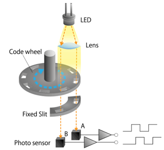
Figure 1: Schematic of Optical Encoder Principle
When the code disk rotates, it generates two typical square waves, A and B, in quadrature pulses, which can be used to determine the rotation and speed of the shaft. When the optical encoder rotates forward, phase A leads phase B by 90 degrees; when it rotates backward, phase A lags phase B by 90 degrees. In other words, the optical encoder determines the specific position and calculates the motion speed based on the number of output pulses, while the direction of gear movement is determined by the phase difference between the A and B pulse signals. Details are shown in the figure below: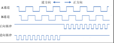
Figure 2: Typical Optical Encoder A and B Channel Diagram
Advantages and Disadvantages of Optical Encoders:
Advantages: Small size, high precision, inherently high resolution (up to 25 bits), no contact wear, and fast response.
Disadvantages: Susceptible to contamination, which can cause discontinuous or lost square wave signals; limited LED lifespan; and the glass or plastic code disk can be damaged by vibration or extreme temperature environments.
2. Magnetic Encoder: Mainly composed of a code disk, magnetic sensing elements, adjustment circuits, power lines, and differential signal lines. The code disk is a magnetized disk with a certain number of magnetic poles distributed evenly along its circumference, alternating in polarity. Magnetic sensing elements, typically Hall elements or magnetoresistive elements, detect changes in the magnetic field caused by the rotation of the disk. The adjustment circuit processes the signals through amplification, frequency division, and multiplication for recognition by the system controller.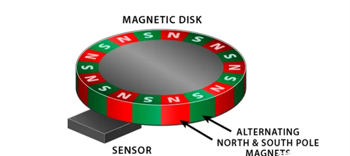
Figure 3: Schematic of Magnetic Encoder Principle
Advantages and Disadvantages of Magnetic Encoders:
Advantages: More durable, resistant to vibration and impact. For example, in the presence of dust, dirt, or oil, the performance of optical encoders significantly decreases, whereas magnetic encoders remain unaffected.
Disadvantages: Electromagnetic interference from motors can significantly affect magnetic encoders, and temperature changes can cause position drift. Their resolution and accuracy are relatively lower.
3. Inductive Magnetic Encoder: Uses non-contact, magnet-free sensing technology to measure the position of a conductive target. It measures the coupling between excitation and receiver coils through a rotating target. Typically composed of a stator and rotor, the stator PCB includes excitation coils, receiving coils, decoding circuits, and communication circuits, while the rotor PCB contains a metal reflector or low-permeability metal.
Figure 4: Schematic of Inductive Encoder
Below is an example using the onsemi NCS32100 solution: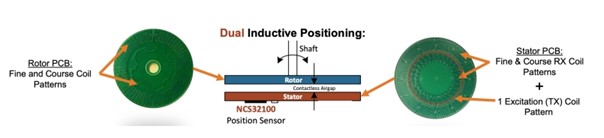
Figure 5: NCS32100 Inductive Encoder Stator and Rotor
The rotor has coarse and fine coil windings, while the stator has receiving and excitation coils. The NCS32100 sends a sine wave to the excitation coil, generating a magnetic field around the stator excitation coil. According to Faraday's law of mutual induction, the rotor's coil windings interact with the electromagnetic field, coupling energy into the rotor coils to form eddy currents. As the rotor rotates, its eddy currents interfere with the stator's receiving coils. The NCS32100's internal DSP processes these interferences to determine the rotor's position.
Advantages and Disadvantages of Inductive Encoders:
Advantages: Can withstand high levels of vibration and contamination, insensitive to magnetic fields, and offers high precision.
Disadvantages: The precision coils result in high production costs.
Classification by Working Principle:
Based on different working principles, encoders can be divided into incremental and absolute types.
Working Principle of Incremental Encoders (using optical encoders as an example):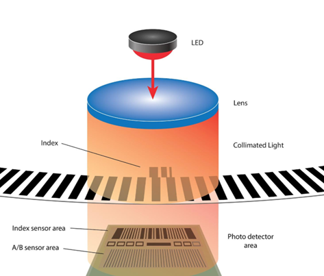
Figure 6: Structure of Incremental Optical Encoder
The code disk is divided into equally spaced opaque lines and transparent windows. One opaque line and one transparent window form a cycle, corresponding to one high level and one low level in the waveform, representing a 360-degree electrical cycle.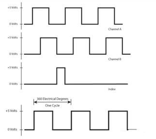
Figure 7: Waveform of Incremental Encoder
From the introduction of optical encoders above, we know that position information must be detected while determining whether the motor is rotating forward or backward. This requires two sensors. Let’s look at the detailed diagram below:
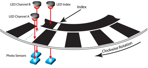
Figure 8: Detailed Diagram of Incremental Encoder Principle
Combining the previous content, we can roughly understand the working principle of incremental encoders: finding the zero position through the index, calculating the rotation angle through the number of pulses, determining the rotation direction through the relative lag of the AB channels, and judging the speed through the time occupied by the waveform or pulse frequency.
What about absolute encoders?
Let’s first look at a schematic of an absolute rotary encoder: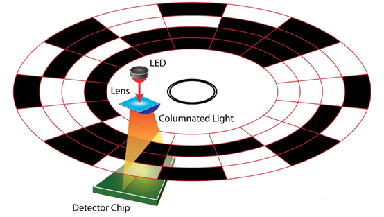
Figure 9: Principle Diagram of Absolute Rotary Encoder
This diagram shows a 16-bit absolute encoder. The entire circle is divided into 16 sectors, and each sector is further divided into four parts along the same radius. An LED shines light from one side of the code disk, and a detection chip on the other side senses the light. Transparent areas allow light to pass through, while opaque areas block it. The presence or absence of light is represented by 1 and 0, respectively, which can then be combined into unique codes.
For example, in the diagram below, the codes can be represented as 0001 and 0101, which correspond to positions 1 and 5 in decimal notation.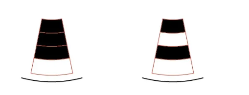
Figure 10: Encoding Method of Absolute Encoder
Thus, the principle of absolute encoders can be summarized as follows: each position has a unique code, which is identified by sensors to output a corresponding unique signal representing a specific position. The "absolute" in absolute encoders refers to the uniqueness, reliability, and stability of the data, not to power-off memory. It is similar to being factory-coded. If higher resolution is required, the code disk must be enlarged.
How does the output waveform of an absolute encoder differ from that of an incremental encoder?
Absolute encoders use pulse width modulation. Taking an optical absolute encoder as an example, a typical absolute encoder output waveform is shown below: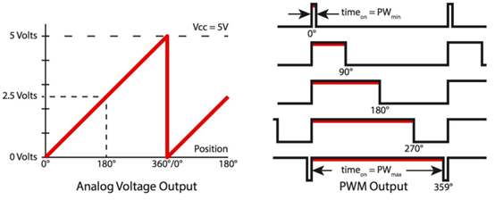
Figure 11: Output Waveform of Absolute Encoder
A 10-bit encoder can output 2^10 = 1024 unique codes. The specific position of an absolute position encoder is represented by pulse width. For example, the starting position is 0, represented by a minimum pulse width unit of 1 μs. At 180°, it is represented by 512 μs. The waveform on the left uses voltage levels to represent different positions, which can be transmitted to the controller for analysis.
How should we choose an encoder?
Selection can be based on:
① Whether absolute position is needed at startup to decide between incremental or absolute encoders;
② Precision requirements and resolution;
③ Cost;
④ Installation method and operating environment.
References:
Classification, principles, and speed measurement applications of encoders (with code) - CSDN Blog
Classification, functions, wiring methods, and principles of encoders - CSDN Blog